Most critical spare parts management strategies are built on instinct rather than evidence. Engineers stock what failed last time, or what the distributor recommended, or what appeared on a generic spares list inherited from a previous contractor. The result is shelves full of low-risk components and nothing available when the failure that actually stops production occurs.
A disciplined failure mode review changes that. It starts with your actual control systems - control panels, PLCs, drives, and protection devices - and works through each component systematically: what happens if this fails, how quickly can it be replaced, and what does it cost the operation while it is down. That analysis produces a spares list grounded in evidence, not assumption.
What a Genuine Electrical Single Point of Failure Actually Looks Like
A single point of failure is not simply a component that could fail. The definition requires three conditions to be met simultaneously: the component's failure causes immediate production stoppage, there is no redundancy or available workaround, and no rapid substitute can be sourced or fabricated.
In practical manufacturing terms, this means the MCB protecting a critical motor circuit, the PLC CPU managing an entire production line, or the variable speed drive controlling a process-critical pump. When any of these components fails without a ready replacement, production does not slow - it stops.
The operational definition of a single point of failure
A single point of failure is any component whose failure causes immediate production stoppage with no available redundancy or rapid substitute. The classification is determined by manufacturing impact and procurement lead time - not technical complexity or component cost alone.
The distinction matters because it changes which components demand attention. A failed indicator lamp is not a single point of failure. A failed safety relay that drops all machine guarding circuits and triggers an E-stop across the line - with a four-week replacement lead time - absolutely is. Failure mode analysis must be anchored in production consequence, not component classification.
How to Conduct a Structured Failure Mode Review of Your Control Systems
A structured failure mode review works through control system layers in sequence. Starting from the incoming supply and working through to field devices, the review assesses each component category against two questions: what is the consequence of failure, and what is the realistic time to restore?
The review must cover the following component categories without exception:
- Control panels and motor control centres (MCCs) - busbars, incoming protection, outgoing circuit devices, and terminal assemblies
- PLC CPU modules, I/O modules, and communication cards - across Siemens, Allen-Bradley, and RDM platforms
- Variable speed drives and soft starters controlling process-critical loads
- Contactors and motor starters, particularly those running at high cycle rates or in thermally demanding environments
- Protection devices including MCBs, RCDs, and overload relays
- Communication interfaces between control layers - Profibus, Profinet, EtherNet/IP, and DeviceNet links where a single card failure can isolate entire machine groups
For each component, record the manufacturer, model reference, current firmware or hardware revision where applicable, and the installation date. Then document the procurement lead time from your primary supplier - and verify it, because catalogue lead times and actual delivery lead times diverge significantly for industrial components.
Catalogue lead times are not reliable planning data
Distributor websites commonly display optimistic lead times based on normal stock levels. For industrial control components - particularly PLC modules, specialist drives, and custom-wound motors - actual delivery following a breakdown can be substantially longer. The failure mode review must use verified lead times obtained from direct supplier enquiry, not catalogue estimates.
Mapping Component Failure to Production Impact: Building Your Criticality Assessment
Criticality assessment has two dimensions, and a component must be assessed against both before its position on the spares list is determined.
The first dimension is likelihood of failure - determined by component age relative to rated lifecycle, operating environment (thermal loading, vibration, humidity, contamination), and condition data from maintenance records and inspection history. A 12-year-old drive in a flour mill environment carries a fundamentally different failure probability than the same model installed two years ago in a clean, temperature-controlled control room.
The second dimension is consequence of failure. Map each component to the production lines it serves, the downtime duration a failure would generate, and any regulatory exposure the stoppage creates. A failed drive on a secondary conveyor that can be manually bridged is a different risk class from a failed PLC CPU that halts an entire automated packing line with no manual override.
Two-dimension criticality matrix: how components are ranked
Likelihood of failure is determined by component age relative to rated lifecycle, operating environment conditions, and condition data from maintenance records. Consequence of failure is determined by the production lines served, the downtime duration a failure generates, and any regulatory exposure created. Components that score high on both dimensions are Tier 1 candidates requiring on-site spares. Components with high consequence but lower current failure likelihood still require active management where procurement lead times are extended — the window to procure narrows once deterioration accelerates.
Criticality assessment data requirements per component
- Installation date and manufacturer-rated operational lifecycle
- Operating environment conditions: temperature, vibration, contamination class
- Production lines directly dependent on this component
- Estimated downtime duration if component fails and no spare is held
- Verified procurement lead time from primary and secondary suppliers
- Regulatory or food safety consequences of an extended stoppage
- Manufacturer end-of-life or obsolescence status
Components that score high on both dimensions - high failure likelihood and high consequence - are immediate Tier 1 candidates. Components with high consequence but lower current failure likelihood still require active management if their lead times are extended, because the window to procure narrows once deterioration accelerates.
Why Bespoke and Manufactured-to-Order Components Carry the Highest Risk
Standard catalogue components - contactors, MCBs, common drive models - can often be sourced within days from distributor stock. Bespoke and manufactured-to-order components operate in a completely different procurement environment, and this is where facilities are most exposed.
The highest-risk categories in most industrial facilities include:
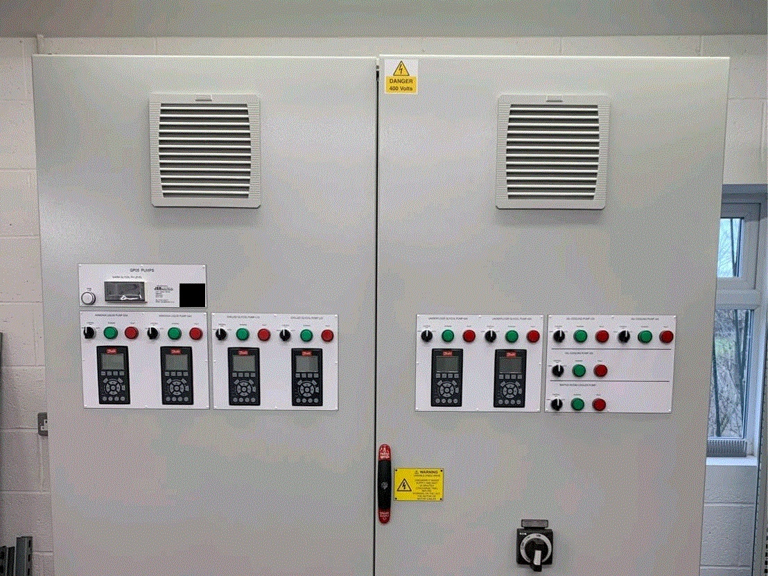
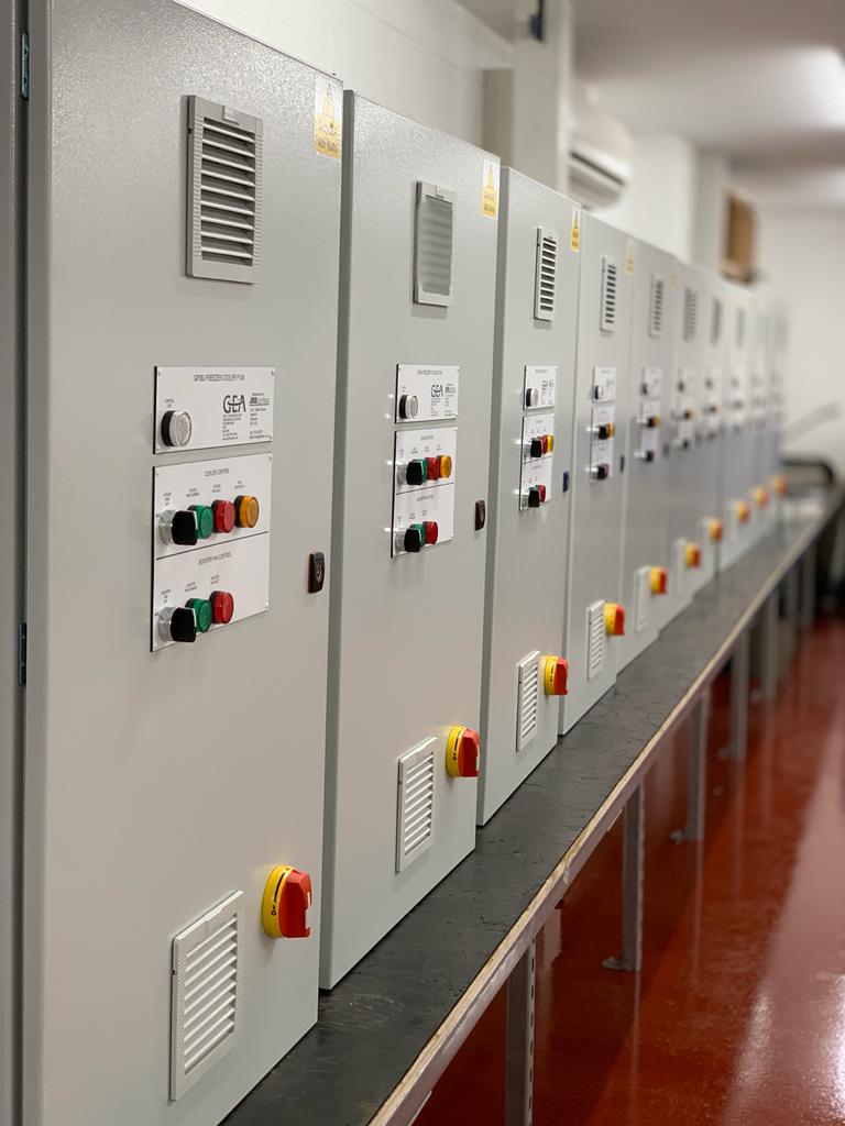
- Custom-built control panels manufactured to a site-specific design - replacements require access to original schematics, component sourcing, assembly, and testing before installation
- Specialist motor windings for non-standard frame sizes, voltages, or enclosure ratings where rewind or replacement lead times extend to weeks
- Legacy PLC modules for discontinued Siemens S5, Allen-Bradley SLC 500, or older RDM platforms where manufacturer stock is exhausted and secondary-market availability is uncertain
- Site-specific HMI screen assemblies with custom faceplates or integrated control interfaces
- Engineered protection relays configured to site-specific protection schemes
Why bespoke components cannot be treated as catalogue items
A standard contactor or MCB can be sourced within days from distributor stock. A custom-built control panel, a specialist motor winding for a non-standard frame size, or a legacy PLC module for a discontinued platform operates in a fundamentally different procurement environment. For bespoke components, the critical question is not simply whether a unit exists — it is whether the original schematics, component specifications, and commissioning documentation are accessible, and whether the realistic build, test, and installation timeline is tolerable during a production stoppage. In most cases, it is not.
Illustrative scenario - legacy PLC module failure
Consider a food processing line running on a legacy PLC platform where the CPU module has been discontinued by the manufacturer. The facility holds no spare. A failure occurs on a Friday afternoon. Secondary-market sourcing identifies a potential unit in Germany, but lead time to delivery and recommissioning extends the line stoppage into the following week. Had the criticality review flagged the obsolescence status, a managed migration to a supported platform - or a held spare with a tested configuration backup - would have reduced recovery time to hours. This scenario is representative of the engineering pattern JBB encounters in facilities where spares strategy has not kept pace with platform lifecycle.Illustrative example based on representative JBB project work.
Manufacturer end-of-life notices and obsolescence alerts must be integrated into the failure mode review. A component approaching end of manufacturer support is not just a spares problem - it is a replacement programme trigger. The review must identify whether a managed platform migration is more appropriate than maintaining a diminishing secondary-market spares position.
Using Thermal Imaging and Power Quality Data to Predict Imminent Failures
Failure mode analysis based solely on age and specification data will miss components that are deteriorating ahead of their expected lifecycle endpoints. Condition data from thermal imaging surveys and power quality analysis provides the early-warning signal that brings those components into view.
Thermal imaging of switchgear, control panels, and terminal assemblies identifies hotspots that indicate loose connections, unbalanced loading, or component degradation before they reach failure threshold. A busbar connection running significantly above ambient temperature is a candidate for the critical spares list and for immediate maintenance intervention - regardless of its apparent age or service history. The thermal imaging data does not replace the failure mode review; it feeds directly into the likelihood-of-failure dimension of the criticality assessment.
Power quality analysis adds a second predictive layer. Harmonic distortion levels, voltage imbalance, and transient events place drives, power supplies, and protection devices under sustained electrical stress that accelerates component degradation. A drive on a supply with high harmonic content is consuming its operational life faster than its rated lifecycle suggests - and the power quality data makes that acceleration visible before it becomes a failure.
Condition data changes which components need immediate attention
A three-year-old drive on a distorted supply may represent higher near-term failure risk than a ten-year-old drive on a clean, balanced supply with a documented maintenance history. Thermal imaging and power quality data surface that reality. Spares lists built without condition data will systematically miss components whose deterioration is environment-driven rather than age-driven.
Both thermal imaging surveys and power quality analysis are embedded in JBB Electrical's preventive electrical maintenance programme. The findings from each survey should be reviewed against the live critical spares list and used to trigger re-assessment of any component whose condition has changed materially since the previous inspection.
Translating Your Failure Mode Analysis Into a Prioritised Critical Spares List
The output of the failure mode review is a tiered spares list, structured by criticality and procurement risk. Three tiers are sufficient for most industrial facilities:
- Tier 1 - Immediate availability on-site: Components whose failure causes immediate, extended production stoppage with no workaround and no rapid external procurement route. These are held in your facility's own secure storage with commissioning documentation and configuration backups available alongside the component.
- Tier 2 - Agreed supplier lead time with forward order placed: Components where failure is serious but the consequence allows a defined recovery window. A confirmed supply agreement with a stated maximum delivery time, reviewed and re-confirmed periodically, is the minimum standard.
- Tier 3 - Obsolescence-managed with replacement programme active: Components already approaching or past manufacturer end-of-life where the long-term strategy is platform migration, not spare accumulation. These require an active programme timeline, not just a stocked unit.
Replenishment triggers must be defined at the point of list creation. A critical spares list without defined replenishment logic becomes static and ineffective within twelve months as components are consumed, conditions change, and supplier relationships evolve.
Each Tier 1 item requires three defined triggers: a minimum stock level below which replenishment is automatic, a consumption event protocol that initiates reorder immediately after any spare is used, and a periodic review interval - typically aligned with the annual maintenance programme - to reassess criticality rating as conditions change.
Three replenishment triggers every Tier 1 item requires
Minimum stock level: the quantity below which replenishment initiates automatically, regardless of whether a failure event has occurred. For most single-unit Tier 1 components, this is one — the trigger fires the moment that spare is consumed. Consumption event protocol: the defined action taken immediately after any Tier 1 spare is used, ensuring the period of highest vulnerability following a failure is closed as quickly as possible. Periodic review interval: a scheduled reassessment — typically aligned with the annual maintenance programme — that re-evaluates whether each component still belongs in Tier 1 as supplier relationships, lead times, and platform lifecycle status change.
Spares documentation is as critical as the component itself
A Tier 1 PLC module held in storage without a verified configuration backup, installation procedure, and commissioning checklist will not restore production quickly. Every Tier 1 spare must be accompanied by the documentation required to install and commission it under pressure - because the failure that requires it will not occur during scheduled downtime.
The JBB Critical Spare Parts Management Methodology
The JBB Critical Spare Parts Management Methodology
Assess
JBB Electrical conducts a structured failure mode review of all control system layers - control panels, PLC platforms (Siemens, Allen-Bradley, and RDM), variable speed drives, contactors, protection devices, and communication interfaces - mapping each component to its production consequence and verified procurement lead time. Thermal imaging surveys and power quality analysis are used to identify components deteriorating ahead of their rated lifecycle, ensuring the criticality assessment reflects actual condition rather than assumed age.
Modernise
Where the failure mode review identifies legacy PLC modules, discontinued protection devices, or custom-built control panel assemblies on obsolete platforms, JBB Electrical develops a managed migration plan - replacing single points of failure with supported, maintainable components before physical failure forces an emergency response. In-house manufacturing capability enables replacement control panels to be designed, built, tested, and documented to site-specific requirements without extended lead times.
Protect
JBB Electrical establishes a tiered critical spares inventory - Tier 1 on-site holdings, Tier 2 supplier agreements, and Tier 3 obsolescence programmes - with installation procedures, configuration backups, and commissioning checklists stored alongside each Tier 1 component. As-built schematics are produced in EPLAN Electric P8 and held alongside panel test records, ensuring replacement and recommissioning can proceed from accurate, current documentation. BS 7671 compliance status of control panels and distribution boards is verified as part of the same assessment, ensuring the protection scheme supporting critical circuits is sound.
Prevent
Scheduled thermal imaging surveys and power quality analysis are integrated into the preventive electrical maintenance programme, with findings reviewed against the live critical spares list after each inspection. Replenishment triggers - minimum stock levels, consumption event protocols, and review intervals - are defined at list creation and enforced systematically, preventing the spares strategy from becoming static as conditions change.
Support
JBB Electrical provides ongoing component lifecycle monitoring, manufacturer end-of-life alert management, and proactive obsolescence planning across the critical spares estate. As a NICEIC-approved contractor founded in 1966, the team that designs and specifies the spares strategy is the same team that maintains and updates it - eliminating the accountability gaps that arise when design, manufacture, and installation are divided between different contractors.
Next Step: Request a Compliance & Breakdown Prevention Assessment
Next Step: Request a Compliance & Breakdown Prevention Assessment
A Compliance & Breakdown Prevention Assessment identifies the electrical, compliance, and breakdown risks affecting your operation, and sets out the engineering actions needed to reduce downtime, protect reliability, and keep your infrastructure defensibly compliant. Request a Compliance & Breakdown Prevention Assessment today to identify your electrical single points of failure and build a prioritised critical spares list grounded in evidence rather than assumption.
Compliance & Breakdown Prevention Assessment