In a temperature-critical environment, electrical design is not a background discipline - it is part of your product protection strategy. A single loose termination, overloaded circuit, or poorly designed control interface can trigger a cascade: refrigeration trips, temperature excursions, product holds, audit failure, and unplanned downtime. Temperature-critical environments are found across various industries such as food storage, pharmaceuticals, and laboratories, where maintaining controlled conditions is essential.
💡 Key Insight: In temperature-critical operations, the real engineering challenge is not “can it run?” - it is “can it keep running safely, compliantly, and predictably under fault conditions?”
What counts as a temperature-critical environment?
Temperature-critical environments are sites where temperature stability is directly tied to safety, quality, compliance, or financial loss. Typical examples include:
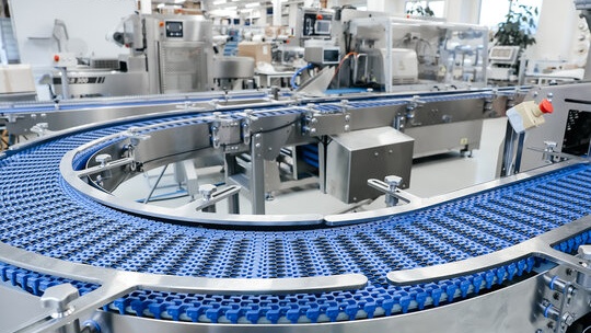
Food manufacturing (chilled processing, freezing, hygienic production areas)
Cold storage and distribution (multi-zone stores, blast freezers, dispatch bays)
Pharmaceutical and biotech (controlled storage, validated monitoring)
Process engineering environments where cooling is production-dependent
Sites with multi-zone temperature control and audit requirements
Large-scale facilities and factories where complex electrical infrastructure supports temperature-sensitive operations
Definition: Temperature excursion s any deviation outside specified temperature limits for a defined duration. The electrical system must be designed to prevent excursions and to detect, alarm, and evidence events when they occur.
The risks electrical design must control
Electrical systems in temperature-critical sites fail in ways that are often predictable. In addition to these predictable failures, it is crucial to identify and mitigate potential hazards through regular inspections, proper equipment installation, and proactive safety measures to prevent incidents.
The risk comes from two places: (1) the failure mode itself and (2) the site’s reduced tolerance for recovery time.
1) Product loss and contamination risk
If refrigeration stops and temperature rises, you can lose stock, compromise quality, and trigger traceability events. In hygienic areas, electrical faults can also become contamination risks if they cause uncontrolled shutdowns or unsafe restarts. Maintaining strict health and safety standards is crucial to protect both personnel and product integrity in these environments.
Cold rooms are essential for storing perishable food items, which extends their shelf life and prevents spoilage.
2) Compliance and audit failure
Many sites must evidence temperature control, alarm response, maintenance, and electrical safety. Weak documentation integrity (missing drawings, undefined circuits, unknown protection settings) creates audit exposure - even if “it’s been running fine”. Meeting regulatory requirements is essential to ensure operational resilience and reduce compliance risks. Businesses benefit from maintaining detailed documentation and records for compliance and asset management.
3) Downtime and cascading plant disruption
Electrical issues rarely stay isolated. A failed control panel supply can stop compressors, which affects suction pressure, which affects multiple zones, which affects dispatch schedules and production planning. Establishing reliable processes is essential for maintaining system uptime and preventing such disruptions in temperature-critical environments.
⚠ Common mistake: Treating refrigeration power and refrigeration control as separate projects. In temperature-critical environments, they must be engineered as one joined reliability system - power, control, instrumentation, alarms, and response.
Design principles for compliance, uptime, and risk prevention
Below are the core engineering principles that consistently reduce failure risk in temperature-critical electrical systems.
Maintaining system reliability and safety is a shared responsibility among all team members and stakeholders. Drawing on expert electrical guides and operational resources helps teams embed consistent practices. Fostering a culture of reliability within teams enhances overall uptime by promoting shared responsibility.
Reliability-First Electrical Design Framework (Temperature-Critical Sites)
Continuity - design for continuous operation and controlled recovery after faults.
Selectivity - ensure protective devices isolate the smallest possible section during a fault.
Visibility - instrumentation and monitoring must make failures diagnosable, not mysterious.
Maintainability - panels, containment, isolation, and labelling must support safe intervention, with regular evaluation of the effectiveness of maintenance strategies.
Documentation integrity - drawings, schedules, test results, and settings must match the installed reality, and the effectiveness of documentation practices should be periodically assessed.
Lifecycle resilience - avoid designs that depend on obsolete components or unsupported software.
Automation of routine tasks is central to maintaining uptime and reducing human error.
Power architecture: design for fault containment
A temperature-critical electrical system should fail gracefully. That means faults are contained and recovery is controlled. In practice, this involves:
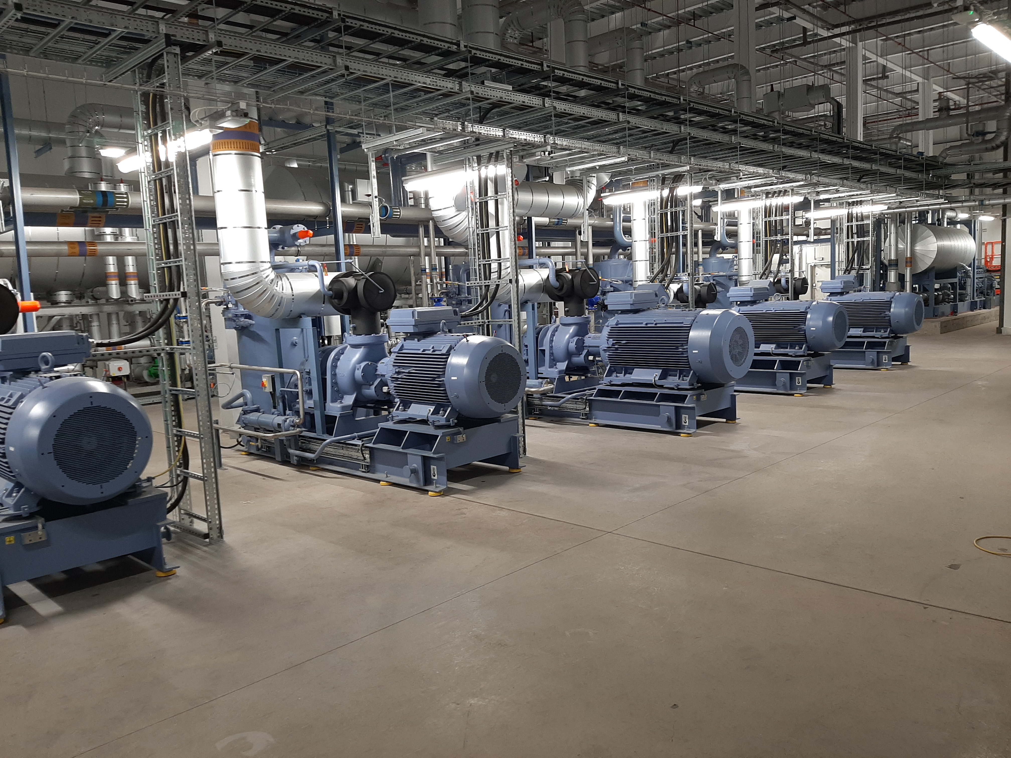
Segregated supplies for refrigeration plant, controls, monitoring, and site-critical auxiliaries, with the power supply as the primary source feeding into the electrical panels and switchgear.
Selective protection coordination to prevent upstream trips taking out entire systems, ensuring that circuit breakers and fuses protect against faults such as short circuits to maintain electrical safety.
Robust earthing and bonding suited to industrial and washdown environments.
Appropriate short-circuit capacity calculations and device ratings for real fault levels.
❗ Important: If a single upstream protective device trip can effect refrigeration across multiple zones, your electrical design is carrying an avoidable single point of failure.
Control panels: engineered for uptime, not just functionality
Control panels in temperature-critical environments should be designed to withstand continuous duty, heat, vibration, and maintenance intervention. It is essential to protect critical components from heat and other environmental factors to ensure system reliability and uptime. Key considerations include:
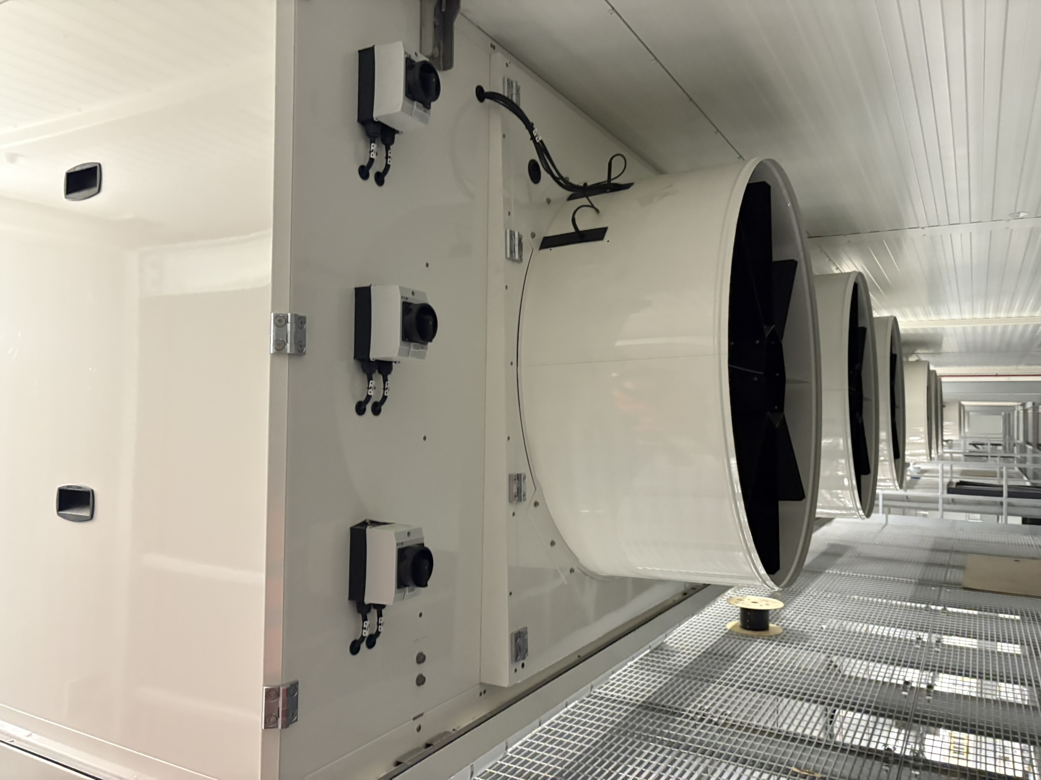
Thermal management (heat load calculations, ventilation or cooling where required, component spacing). The internal temperature in many general electrical enclosures should stay below 35°C (95°F) to ensure reliable operation.
High-quality terminations with correct torque, ferrules, and inspection access.
Logical segregation (power vs control, analogue vs digital I/O, safety circuits).
Clear isolation strategy for safe fault finding without uncontrolled shutdowns.
Ingress protection and materials appropriate to wet or hygienic areas.
🚫 Pitfall: Building panels that are “compact” but not serviceable. In the real world, cramped panels increase fault time because engineers cannot isolate and test safely under pressure.
If you are modernising panels, ensure the build is aligned with industrial panel standards (commonly including BS EN 60204-1 where relevant to machinery and control assemblies) and that documentation is delivered as-built, not “intended”.
Relevant JBB service: Control Panels
Instrumentation and temperature monitoring: design the alarm chain end-to-end
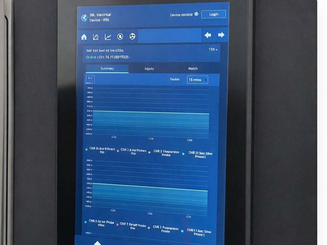
Temperature monitoring is not just a sensor choice. It is a chain: sensor accuracy, wiring integrity, input scaling, logging, alarming, escalation, and response. In temperature-critical environments, it is essential to continuously monitor system status and temperature. Your design should define:
Sensor strategy (placement, redundancy for critical zones, calibration approach). Temperature sensors like NTC thermistors and thermocouples are used to monitor temperatures at critical points.
Signal integrity (screening, routing, segregation from noise sources, and correct grounding practices).
Alarm philosophy (thresholds, delays, latching, nuisance alarm prevention).
Escalation (who is notified, in what order, how acknowledgement is captured).
Evidence (logs, timestamps, audit exports, exception reporting).
🧪 Example: A cold store may run “stable” for months, then lose a door heater circuit or defrost control input that causes gradual icing. Without the right monitoring and alarms, the first sign is a system failure.
PLC, SCADA, and software lifecycle: build for supportability
Many failures in temperature-critical sites are “software adjacent” - the hardware is fine, but the site cannot diagnose, change, or recover because the control system is obsolete, undocumented, or locked to a single engineer’s laptop.
When designing or upgrading automation, engineer for:
Version-controlled PLC code with clear change history and rollback options.
Readable alarm and fault logic (what failed, why, what to check first).
Safe restart and recovery routines to prevent damaging short-cycling or unsafe sequencing.
Remote visibility where appropriate - not to replace engineers, but to shorten time-to-diagnosis. Data collected through metrics, logs, and traces supports proactive monitoring, quick incident resolution, and predictive maintenance by helping teams determine the right maintenance timing.
Spare capacity in I/O and network design so future sensors and zones can be added cleanly.
Smart systems with IoT enable real-time monitoring and automated control adjustments based on data analytics.
ℹ Design tip: Write your fault handling logic as if you will be diagnosing it at 02:00 during a breakdown. If the system cannot tell you what happened, recovery becomes guesswork.
Relevant JBB service: PLC Software
Compliance considerations that shape electrical design
Temperature-critical environments sit under multiple compliance pressures. The exact set depends on your sector, but the engineering outcome is consistent: you need demonstrable control, safe electrical infrastructure, and audit-ready documentation. It is essential to ensure that all electrical equipment is operating within the required safety and compliance standards to maintain reliable and safe electrical systems.
Electrical safety and certification
Your installation should be designed, installed, inspected, and tested to the applicable standards and site requirements. In the UK, industrial electrical installations commonly reference BS 7671 and are supported by appropriate inspection and certification regimes. It is essential to ensure secure energy isolation and safeguarding of equipment to prevent accidents and unauthorized access in the workplace. The practical design impact includes correct circuit design, protective device selection, and proper electrical testing and certification records.
Machinery and control assemblies
Where control panels and machinery interfaces are involved, design and build standards for control equipment matter. Proper lighting systems are also essential as part of control equipment design, ensuring safety, visibility, and operational efficiency in temperature critical environments. This influences layout, identification, protection, and documentation quality - all of which affect maintainability and fault time.
Operational compliance: evidence and traceability
Auditors and insurers are rarely satisfied by verbal assurance. They expect evidence: test results, maintenance records, calibration records, alarm logs, and clear drawings. Uptime evidence may also include Mean Time Between Failures (MTBF) as a key measure of system reliability, with uptime metrics such as MTBF supporting audit readiness through maintenance records. Ongoing training for personnel is essential to ensure proper documentation and compliance with operational standards. If your electrical and control system documentation cannot be trusted, your compliance exposure increases.
Audit-Ready Documentation Checklist (Electrical + Control)
✅ Up-to-date single line diagrams and distribution schedules
✅ As-built panel drawings and I/O schedules
✅ Protective device settings recorded and controlled
✅ Test results and certification are accessible and current
✅ Temperature monitoring logs and alarm history exportable
✅ Maintenance reports with defect prioritisation, documentation of preventive actions, and any repairs performed, along with close-out evidence
✅ Critical spares list and procurement lead-times documented
Preventive measures that stop failures before they become incidents
Designing well is essential, but temperature-critical reliability is maintained over time through preventive measures, including routine inspections. The highest-performing sites treat prevention as an engineered system, not an ad-hoc activity. Structured preventive electrical maintenance programmes are designed to reduce the likelihood of equipment failures and bolster long-term efficiency.
Thermal imaging and condition-led inspections
Overheating connections, overloaded devices, and degrading components often show clear thermal signatures before they fail. Regular thermal imaging surveys for industrial electrical systems can help identify hot spots in electrical panels before they turn into failures, which keeps condition-led inspections focused on corrective action rather than guesswork. Regular inspections are essential for identifying issues with insulation, refrigeration systems, and seals in cold rooms, and the right tools help teams track findings and respond early to maintain system integrity. A structured thermal imaging programme, tied to corrective actions, reduces both breakdown risk and fault duration.
Relevant JBB service: Preventive Maintenance
Critical spares strategy
In temperature-critical operations, lead-time is a risk variable. If a single drive, contactor, PLC module, or sensor can stop refrigeration and you cannot replace it quickly, your downtime exposure is higher than you think. A structured critical spares strategy for essential components should focus on critical components essential for system reliability, ensuring that these vital parts are available to maintain uptime and uninterrupted service.
⚠ Risk reality: The difference between a 45-minute recovery and a 36-hour incident is often a single unavailable component - not the complexity of the fault.
Planned modernisation (lifecycle risk removal)
Ageing panels, unsupported PLCs, and undocumented modifications create “unknown unknowns”. Employing different types of planned modernisation strategies can remove lifecycle risk before it becomes a breakdown.Step-by-step: How to engineer a modernisation plan without disrupting operations
Step 1 - Baseline assessment: capture as-built status, drawings, and current test condition. Following these steps helps achieve optimal system performance and reliability.
Step 2 - Risk ranking: identify single points of failure, obsolete components, and thermal hot spots.
Step 3 - Isolation planning: design changeovers and shutdown windows around production realities.
Step 4 - Build and test: factory test panels and logic where possible before site cutover. A well-executed installation process ensures that the insulation, refrigeration, and all associated components of a cold room work seamlessly together.
Step 5 - Commission and prove: structured commissioning with alarm verification and evidence capture.
How modern systems improve reliability in temperature-critical sites
Modern electrical and control systems improve reliability in four practical ways, helping to maintain system performance and uptime:
Better fault visibility: clearer diagnostics, alarm context, and trending to detect drift before failure.
Reduced single points of failure: improved segregation, selectivity, and redundancy where justified.
Improved maintainability: serviceable panel layouts, safe isolation, and documentation that matches reality.
Faster response: monitoring and escalation that shorten time-to-awareness and time-to-action.
Maintaining uptime safeguards both revenue and reputation, which are critical business assets.
✅ What “good” looks like: When a device fails, the system isolates only what it must, alarms the right people with actionable context, and the engineer can diagnose quickly using drawings and logs that match the installed equipment.
Where JBB fits: engineering support across the full risk chain
JBB Electrical supports temperature-critical operations as a specialist industrial engineering partner, offering a comprehensive range of services including design, installation, control systems, compliance, monitoring, and breakdown prevention. High uptime ensures business continuity by keeping core services available and preventing costly interruptions.
JBB Method: Assess → Modernise → Protect → Prevent → Support
Assess: establish risk visibility - electrical condition, documentation gaps, and lifecycle threats.
Modernise: upgrade panels, protection, and control where obsolescence or poor design increases downtime risk.
Protect: implement monitoring, alarms, selectivity improvements, and safer isolation strategies.
Prevent: embed preventive maintenance, thermal inspections, and spares planning.
Support: provide ongoing engineering backup to help systems perform optimally, with documentation integrity and compliance readiness maintained. Every minute of downtime carries a cost, including lost transactions and disrupted workflows.
Relevant JBB service: Electrical Installations
Practical design review questions to ask before you sign off
Temperature-Critical Electrical Design Sign-Off Checks
✅ If a downstream fault occurs, will the system trip locally - or take out multiple zones?
✅ Are control supplies and monitoring supplies protected from refrigeration power disturbances?
✅ Can engineers isolate safely and quickly without an uncontrolled shutdown?
✅ Are thermal loads inside panels calculated and managed?
✅ Are drawings, schedules, and settings controlled and delivered as-built?
✅ Are alarms meaningful, tested, and linked to an escalation and response process?
✅ Do you have a critical spares list tied to real lead-times?
✅ Has the ability and training of the maintenance crew been verified to ensure they can perform effective preventive maintenance? Training and skill development are essential for maintaining system reliability in temperature-critical environments.
If your site depends on refrigeration, temperature monitoring, or production-critical cooling, the safest approach is to validate the electrical and control system design against real operational risk. JBB’s Compliance & Breakdown Prevention Assessment identifies failure points, documentation gaps, lifecycle risks, and practical upgrades that protect uptime.
Request a Compliance & Breakdown Prevention Assessment - and get a clear, engineering-led plan to improve reliability, strengthen compliance, and reduce downtime exposure and operational costs in your temperature-critical environment.
Book a Compliance & Breakdown Prevention Assessment
If your site depends on refrigeration, temperature monitoring, or production-critical cooling, the safest approach is to validate the electrical and control system design against real operational risk. JBB’s Compliance & Breakdown Prevention Assessment identifies failure points, documentation gaps, lifecycle risks, and practical upgrades that protect uptime.
Request a Compliance & Breakdown Prevention Assessment - and get a clear, engineering-led plan to improve reliability, strengthen compliance, and reduce downtime exposure in your temperature-critical environment.
FAQs: Designing electrical systems for temperature-critical environments
What risks could occur through poor design?
Poor electrical and control design increases the likelihood of uncontrolled shutdowns, nuisance trips, and slow fault recovery. In temperature-critical operations, this can result in higher temperatures within the cold room, leading to temperature excursions, product loss, audit exposure, and downtime that cascades across multiple zones or production lines. Temperature calibration is necessary to ensure that a cold room is kept at the correct temperature, avoiding overworking the system.
How does compliance affect this?
Compliance requirements push you towards evidence, not assumptions. That means inspection and test records, as-built drawings, controlled settings, and provable alarm and monitoring performance. Access control systems also play a crucial role in ensuring compliance and security by regulating entry and maintaining secure environments. If your documentation integrity is weak, your compliance and insurance position can be compromised even if the plant “seems fine”. Incorporating thermal analysis during the design phase helps prevent costly redesigns later.
What preventive measures should be taken?
The highest-impact measures are condition-led inspections (including thermal imaging), a documented critical spares strategy, tested alarm escalation, and a planned modernisation roadmap for obsolete panels or unsupported control platforms.