
Electrical control panel design failures rarely announce themselves during commissioning. They surface six months later, when a production line trips under peak load, or two years later, when an insurer queries a missing test certificate. By then, the panel is installed, the contractor is gone, and the cost of putting it right lands entirely with the facility.
This guide is for facilities managers and operations directors who need a clear framework for what separates a reliable, future-proof control panel from one that causes integration failures, compliance gaps, and costly redesigns within years of commissioning.
Why Control Panel Specification Fails Before a Component Is Fitted
The most common source of control panel problems is not poor manufacturing - it is an incomplete brief.
When a facilities manager specifies a panel based on today's connected load without accounting for growth, duty cycles, or the specific environmental conditions of the installation, the resulting panel is technically compliant on day one and inadequately specified within three years. This is not a manufacturing defect. It is a specification failure.
Specification gaps typically fall into three categories:
- Operational environment underspecified - enclosure IP rating, temperature derating, and vibration tolerance not defined for the actual installation location
- Load growth not modelled - busbar ratings and breaker capacity sized for current load with no provision for additional machinery or production shifts
- Integration assumptions not documented - no defined interface between the panel, the machinery it controls, and the site electrical infrastructure
Each of these gaps can be closed before a single component is ordered - but only if the design process begins with a structured engineering assessment rather than a line-item quotation.
The brief determines the outcome
A panel manufactured to an incomplete brief will pass initial testing and fail in service. The cost of redesign, site disruption, and production downtime substantially exceeds the cost of a thorough upfront specification review.
Specifying for Load, Growth, and Operational Reality - Not Just Today's Requirements
Load calculation is where most under-specified panels originate. The connected load figure is straightforward to obtain - add up the nameplate ratings of every motor, heater, and control circuit. The operational load is more complex, and it is the figure that matters.
Demand factors, duty cycles, and simultaneous start loads all affect what the panel must handle in practice. A manufacturing facility that runs two shifts today but plans a third shift within 18 months needs a panel sized for that future state - not retrofitted at cost later.
The specific consequences of under-specifying are predictable:
- Undersized busbar ratings create thermal stress under peak load, accelerating insulation degradation and increasing the risk of fault conditions at the point of connection
- Breaker capacity specified at connected load with no headroom trips on legitimate operational peaks, causing nuisance shutdowns that interrupt production
- Cable management without spare ways forces a full rewire when additional circuits are needed - what should be a day's work becomes a project
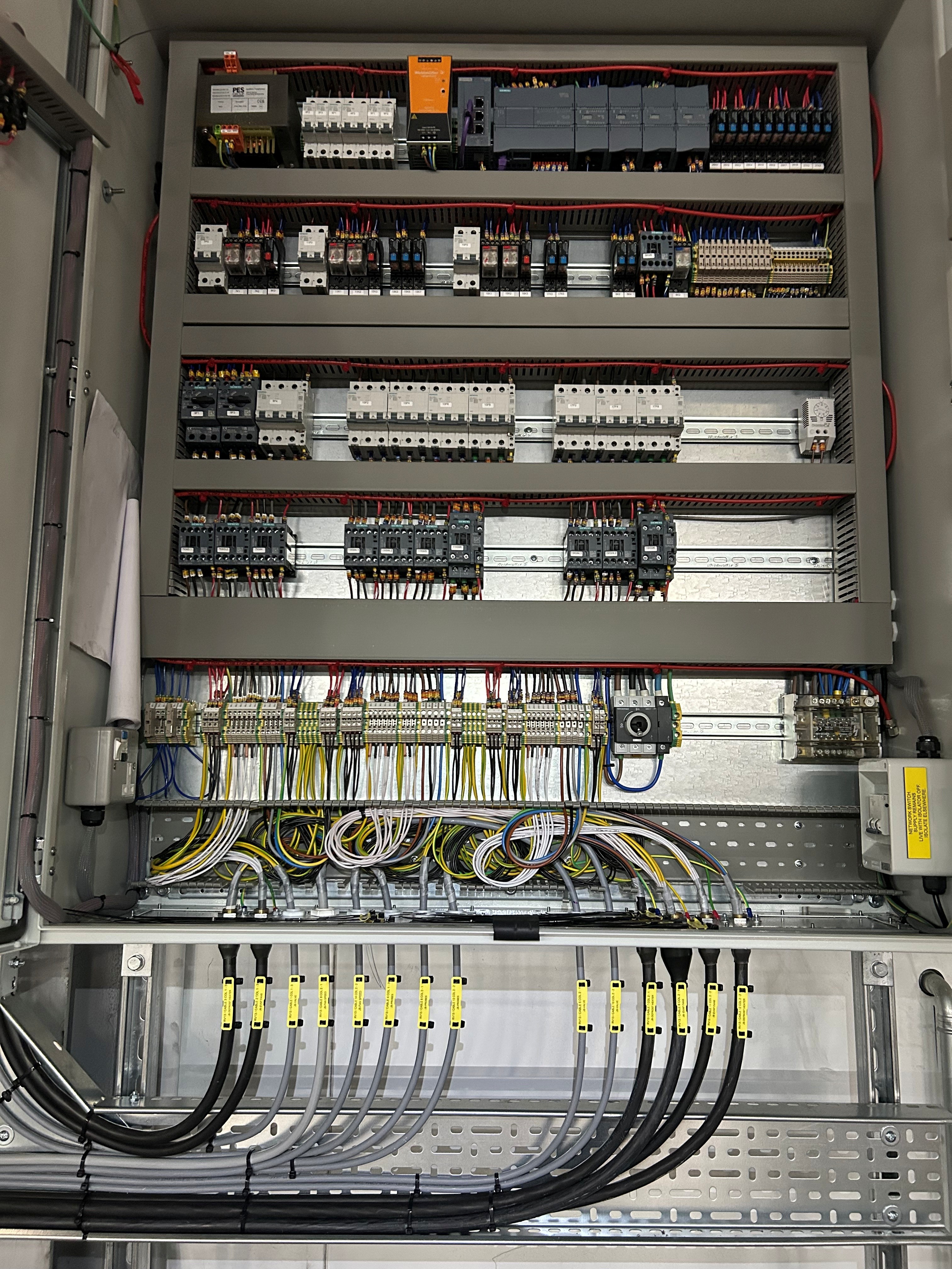
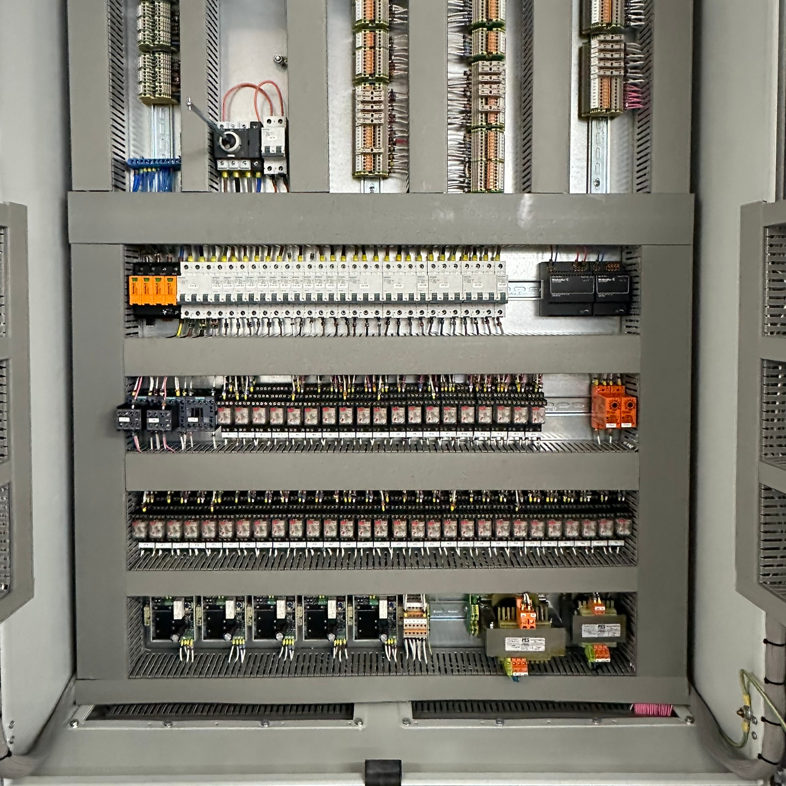
Good panel design builds in provision for what is coming. Spare ways in the cable duct, modular layout that accommodates additional DIN rail sections, and busbar rated to the anticipated future load rather than the current connected load - these are not over-engineering, they are the difference between a panel that serves a facility for its intended lifespan and one that constrains operations within years of installation.
Specify for the facility in three years
When reviewing a panel specification, ask the designer to model the load at anticipated production capacity - not just current requirements. Busbar and breaker sizing decisions made at this stage are significantly cheaper than modifications made under operational pressure later.
Component Selection and Obsolescence Risk: Why Cheap Choices Become Expensive Problems
The instinctive response to a tight capital budget is to reduce component cost. This is the calculation that creates the most expensive panels over a five-year horizon.
Contactor and protection device selection directly affects mean time between failures. A contactor specified at its rated duty and sourced from a manufacturer with a UK-stocked supply chain will outperform a cheaper equivalent specified at the limit of its rating. The cost differential on a bill of materials is modest. The cost differential when a failed contactor requires emergency procurement from an overseas distributor - with a production line down - is substantial.
Obsolescence risk is the dimension most commonly missed during specification. Components specified from manufacturers who have announced product range discontinuation, or sourced from grey market channels, create a specific problem: when replacement is needed, the component is either unavailable or unverifiable. For facilities operating under food safety, pharmaceutical, or insurance audit regimes, an unverifiable replacement component is not an acceptable solution.
Component selection criteria that protect long-term reliability include:
- Duty rating specified with operational headroom - contactors running at a meaningful percentage below their rated capacity run cooler and last longer
- Manufacturer product lifecycle checked at specification stage - components with announced end-of-life dates should not be designed into a panel expected to operate for ten or more years
- UK supply chain availability confirmed - components sourced through stocked UK distributors reduce emergency procurement lead times from weeks to hours
- Protection device coordination verified - upstream and downstream devices must be coordinated so a fault at any point clears without cascading to a wider outage
Illustrative example - representative of the engineering pattern, not a documented JBB project
Consider a food processing facility where a motor control centre was built using contactors sourced from a manufacturer whose product range was discontinued shortly after panel commissioning. Three years into operation, a contactor fails on the primary chiller circuit. The direct replacement is unavailable. A cross-reference to an alternative manufacturer requires a wiring modification the original drawings do not support. The repair takes two days instead of two hours, and the facility operates a manual temperature monitoring regime throughout - with the associated audit documentation burden. The engineering consequence is straightforward: component lifecycle should have been verified at specification stage, with a manufacturer active in UK distribution and holding a minimum ten-year product support commitment.
BS EN 60204-1 Compliance: What It Requires and How It Shapes Panel Design Decisions
BS EN 60204-1 sets mandatory requirements for the electrical equipment of machines. For UK industrial facilities, this is not an advisory standard - it is the engineering baseline against which panel design is assessed, and non-compliance carries direct operational and legal consequences.
The standard governs several panel design decisions that are often treated as preferences rather than requirements:
- Protection against electric shock - the panel must provide physical protection against direct and indirect contact, with enclosure selection verified against the IP rating required for the installation environment
- Protective bonding - all exposed conductive parts must be connected to the protective bonding circuit, with continuity verified and documented
- Control circuit design - emergency stop functions must conform to defined performance levels, with the control circuit designed so that a single fault does not result in loss of the safety function
- Cable identification and marking - every conductor must be identifiable throughout its run, with labelling that matches the schematic drawings supplied with the panel
- Documentation requirements - the standard mandates that technical documentation, including circuit diagrams, be supplied with the equipment
Non-compliance with BS EN 60204-1 has practical consequences that extend beyond a failed inspection. Where a panel is connected to machinery that causes an injury or fire, the absence of compliant documentation - or evidence that the panel was not designed to the standard - directly affects the liability position of the facility operator. BS 7671 compliance through installation does not substitute for BS EN 60204-1 compliance at the panel design level; both standards apply and address different aspects of the electrical system.
The Documentation a Panel Must Ship With - And Why Insurers and Auditors Will Ask for It
A control panel is not a completed deliverable without its documentation package. This is not a bureaucratic requirement - it is the engineering record that allows the panel to be safely modified, maintained, and audited throughout its operational life.
The minimum documentation set for a properly completed panel installation consists of:
- Verified schematic drawings - as-built, not as-designed. Schematics updated to reflect any wiring changes made during manufacture or commissioning, with revision control applied. Insurers and fire investigators will request these. If the drawings do not match the panel, the documentation is not valid.
- Test certificates - functional test results confirming protection devices operate within specification, insulation resistance measurements, and continuity verification for the protective bonding circuit
- Factory Acceptance Test (FAT) records - documented evidence that the panel was tested against the defined specification before leaving the manufacturing facility, signed off by an authorised engineer
- Maintenance schedule - a defined inspection and servicing programme aligned to the duty cycle and environmental conditions of the installation, specifying which components require periodic testing and at what intervals
The maintenance schedule is the document most commonly absent from panel handover packs, and its absence has a predictable consequence: maintenance is performed reactively rather than preventively. Connecting panel documentation to a structured preventive electrical maintenance programme is the step that transforms a static engineering record into an active operational asset.
Auditors request as-built drawings, not as-designed drawings
Schematics that reflect the original design rather than the installed reality are among the most common documentation failures identified during safety inspections. Any modification made between design approval and site commissioning must be recorded in the drawing revision history before the panel is handed over.
How a Design-Through-Commissioning Process Eliminates Post-Installation Integration Gaps
Integration failures - where a correctly manufactured panel does not operate correctly once connected to the site infrastructure or the machinery it controls - are among the most disruptive and expensive post-installation problems a facility encounters. They are also among the most preventable.
The root cause is almost always an accountability gap. When panel design, manufacture, installation, and commissioning are handled by different contractors, each working from their own interpretation of a specification, the interfaces between disciplines are where problems collect. The panel designer assumed the installer would verify earthing continuity. The installer assumed the commissioning engineer would test the emergency stop circuit. The commissioning engineer assumed the panel manufacturer had configured the overload relay settings. None of these assumptions were documented.
A single contractor managing design through commissioning eliminates this risk at the source. When the same team designs the schematic, manufactures the panel, integrates it into the site electrical system, and commissions it against a defined functional test protocol, there are no interface gaps for assumptions to fill. JBB Electrical operates on exactly this basis - same team: design, build, test, document - eliminating the accountability gaps that arise when design, manufacture, and installation are divided between different contractors.
The integration gap is a structural problem, not a contractor quality problem
Dividing design, manufacture, and commissioning between separate contractors does not create a quality problem at any individual stage - it creates an interface problem between stages. Specifying a single contractor with in-house manufacturing capability and site installation resource removes the structural cause of integration failures.
The practical scope of a design-through-commissioning engagement covers: schematic design using EPLAN Electric P8, component sourcing verified against UK supply chain availability, panel manufacture with quality testing at each stage, installation coordinated with mechanical trades to avoid service conflicts, and commissioning against a documented functional test protocol that becomes part of the handover documentation.
The JBB Electrical Control Panel Design Methodology
The JBB Electrical Control Panel Design Methodology
Assess
JBB engineers conduct a structured review of the facility's connected load, operational duty cycles, environmental conditions, and growth requirements - establishing the busbar ratings, enclosure IP classification, and protection coordination framework before a schematic is drawn. This assessment also identifies BS EN 60204-1 obligations specific to the machinery being controlled and any BS 7671 interface requirements at the point of supply.
Modernise
Where an existing panel is being replaced or upgraded, JBB's in-house manufacturing capability delivers a redesigned solution using current-generation components sourced through verified UK supply chains - replacing obsolete contactors, protection relays, and HMI interfaces with equivalents that carry confirmed product lifecycle support. Schematic design is produced in EPLAN Electric P8, ensuring documentation quality meets audit and insurance requirements from the outset.
Protect
Panel design incorporates protection device coordination verified across all downstream circuits, emergency stop circuit design to the performance level required by BS EN 60204-1, and protective bonding continuity documented for every exposed conductive part. Factory Acceptance Test records are produced before the panel leaves the manufacturing facility, establishing a verifiable baseline for ongoing maintenance and compliance assessment.
Prevent
Spare ways in cable management, modular DIN rail layout, and busbar rated to anticipated future load are built into every panel design - so additions required by production expansion are made without full rewiring. A maintenance schedule aligned to the duty cycle and environmental conditions is supplied with the panel, integrating directly with the facility's preventive electrical maintenance programme to identify deteriorating contactors and protection devices before they cause unplanned downtime.
Support
JBB provides complete handover documentation - as-built verified schematics, test certificates, FAT records, and maintenance schedules - and remains available for post-commissioning technical support. As a NICEIC-approved contractor with in-house manufacturing experience dating to 1966, JBB's ongoing relationship with each facility ensures that regulatory updates and equipment additions are incorporated into the panel design record rather than accumulated as undocumented field modifications.
Next Step: Request a Compliance & Breakdown Prevention Assessment
Next Step: Request a Compliance & Breakdown Prevention Assessment
A Compliance & Breakdown Prevention Assessment identifies the electrical, compliance, and breakdown risks affecting your operation, and sets out the engineering actions needed to reduce downtime, protect reliability, and keep your infrastructure defensibly compliant. Request a Compliance & Breakdown Prevention Assessment today to ensure your control panel specification, documentation, and compliance position are engineered to support your facility through its next phase of operation.
Compliance & Breakdown Prevention Assessment