Most PLC control panel briefs start in the wrong place. Cabinet dimensions, mounting arrangements, cable entry positions - these are logistical concerns, not engineering ones. The design decisions that determine whether a panel performs reliably for 15 to 20 years happen at specification stage, long before the first component is ordered.
Fault protection levels, environmental ratings, busbar capacity, documentation standards, expansion provisions - get these right and the panel becomes a stable platform for your automation infrastructure. Get them wrong and the panel becomes a recurring source of downtime, a compliance liability, and an obstacle to every future production change.
This article gives operations directors and project engineers a framework for specifying PLC control panels that deliver on both counts - performance and longevity - and the questions to ask any supplier before a build begins.
Why the Panel Brief Must Go Beyond Physical Dimensions
A panel brief that stops at cabinet size, IP rating, and mounting requirements has described a box, not a system. The physical enclosure is the least consequential part of what gets specified. The decisions that actually drive long-term reliability are buried in the electrical design - and if they are not in the brief, they will be resolved by the manufacturer based on cost, not consequence.
Every PLC control panel brief for an industrial production environment should specify, as a minimum:
- Fault protection levels - short-circuit rating of the assembly, upstream fuse or breaker coordination, and the discrimination strategy between protection devices
- Environmental rating - IP or NEMA classification matched to the actual installation environment, not defaulted to IP54 because that is what was specified last time
- Thermal management - heat load calculation, forced ventilation requirements, and whether the enclosure can maintain component operating temperatures in summer ambient conditions
- Future expansion provisions - spare ways, busbar headroom, cable management capacity, and I/O card slots reserved for foreseeable production changes
- Documentation standard - what the panel ships with, in what format, and who holds the master files
The cost of an under-specified brief
Panels built to an incomplete brief are rarely wrong on day one. They become wrong over time - when ambient temperatures rise in summer, when a production line is extended and the busbar has no spare capacity, or when a fault occurs and the documentation does not reflect what was actually installed. Retrospective modifications to address these gaps are substantially more expensive than designing them out at specification stage.
The panel brief is also where the integration context belongs. A PLC control panel that will connect to a SCADA system, remote monitoring infrastructure, or wider automation estate has different communication, earthing, and screening requirements to a standalone controller. These are not afterthoughts - they are design inputs. Addressing them after manufacture typically means rework.
Component Selection: Where Long-Term Reliability Is Won or Lost
The difference between a panel that runs cleanly for two decades and one that generates a fault call every quarter often comes down to component specification. Not PLC platform - components. Breakers, contactors, terminal blocks, and power supplies are where cost-cutting manifests as maintenance burden.
Circuit Breakers and Protection Devices
Undersized or miscoordinated breakers are among the most common root causes of nuisance tripping and downstream damage in industrial panels. The issue is rarely that a breaker is the wrong ampere rating - it is that the breaking capacity has not been sized to the prospective short-circuit current at the point of installation, or that the upstream and downstream devices have not been coordinated to discriminate correctly under fault conditions.
In practice, this means specifying breaker kA ratings based on a short-circuit analysis for the specific installation - not applying a generic figure used on previous projects. A breaker that is not rated for the fault current at that point in the distribution network will fail to interrupt correctly, risking damage to the panel assembly and upstream equipment.
Contactors and Motor Starters
Contactor selection is where the gap between initial build cost and lifetime maintenance cost is most visible. Low-grade contactors installed to reduce panel price typically have lower mechanical and electrical endurance ratings. In a production environment running two or three shifts, a contactor switching ten times per hour accumulates operating cycles quickly. When it fails, the failure is rarely clean - arcing, welded contacts, and control circuit faults are common consequences.
Specifying contactors to the actual utilisation category and operational duty - AC-3 for motor starting, AC-4 for plugging or inching applications - and selecting a mechanical endurance class matched to real cycle frequency is a straightforward decision at design stage. It becomes a significantly more expensive decision when a replacement is needed during a production run.
Terminal Blocks and Wiring Standards
Non-standard terminal blocks and inconsistent wiring practices create problems that compound over time. Panels built with mixed terminal block types, unlabelled conductors, or non-ferruled terminations are substantially harder to fault-find, modify, and verify during compliance inspections. These are not aesthetic issues - they are safety and maintainability issues.
Illustrative example - representative of the engineering pattern, not a documented JBB project
Motor Control Centre (MCC) panel - During a routine maintenance inspection of a food processing MCC, an engineer conducting thermal imaging identifies a distribution terminal running significantly above reference temperature. Investigation reveals that non-ferruled conductors had been re-terminated during a previous modification, resulting in a high-resistance connection under load. The correct engineering response is to re-terminate using ferrules and crimped connections to the original specification, torquing to the manufacturer's documented value. Left unaddressed, a high-resistance termination at this current level would progress to insulation degradation and potential arcing fault, with the risk of production shutdown and damage to adjacent wiring.
Fault Protection and BS EN 60204-1 Compliance Built to Last
BS EN 60204-1 sets the compliance baseline for the safety of machinery electrical equipment - and it is the standard against which PLC control panels in UK manufacturing and food processing facilities will be assessed. Compliance is not optional, but the way compliance is designed into a panel determines whether it remains valid as regulations evolve or requires remediation at the next audit.
The standard covers protective bonding, isolation and switching provisions, operator interface requirements, fault protection, and the documentation a panel must carry. A panel designed to current BS EN 60204-1 requirements - with PE conductor sizing, emergency stop architecture, and safety relay integration verified against the standard - provides a defensible compliance position at inspection.
What good specification practice adds is forward provision. Regulatory requirements for safety functions, functional safety levels, and documentation are not static. Panels designed with segregated safety circuits, documented safety function performance, and modular safety relay architecture are substantially easier to update when standards are revised - compared to panels where safety functions are integrated into general control wiring without clear demarcation or documentation.
Compliance is a design input, not a commissioning check
BS EN 60204-1 compliance cannot be retrofitted at commissioning. PE conductor sizing, isolation provisions, and emergency stop architecture must be specified in the design - not checked at the end. Panels that pass initial inspection but were not designed to the standard typically reveal compliance gaps when modifications are made or the installation is re-inspected.
The Documentation Package Every PLC Control Panel Should Ship With
The documentation a panel ships with is not an administrative formality. It is the evidence base that supports insurance inspections, safety audits, maintenance decisions, and future modifications. A panel without complete documentation is a panel that cannot be safely modified, reliably maintained, or efficiently fault-found.
Every PLC control panel should ship with, as a minimum, the following documentation package:
Minimum PLC control panel documentation package
- Full electrical schematics - circuit-by-circuit drawings in an editable format, not PDFs only
- Bill of materials (BOM) - every component referenced by manufacturer part number, rating, and physical location in the panel
- Test certificates - insulation resistance, continuity, functional test results, and protection relay test records
- Commissioning records - documented set points, configuration values, and sign-off against the design specification
- PLC configuration backups - version-controlled copies of the control program, with annotation of any site-specific modifications made at commissioning
- Maintenance schedule - recommended inspection intervals, test procedures, and critical component replacement points
The format matters as much as the content. Schematics delivered as PDF only cannot be updated when modifications are made - meaning the as-built record diverges from the installed reality the moment any change occurs. Editable native files (EPLAN Electric P8 format, for example) held by both the manufacturer and the site provide the basis for a documentation set that remains accurate over the panel's service life.
Ask any prospective panel manufacturer to confirm: who holds the master schematic files, in what format, and what the procedure is for updating them after site modifications. If the answer is unclear, the documentation risk belongs to you.
How Panel Design Determines SCADA Connectivity and Fault Response Time
The speed at which a fault condition is identified and resolved is not just an operational variable — it is a design variable. Panel design determines whether a fault produces an immediately actionable alarm or a prolonged process of elimination.
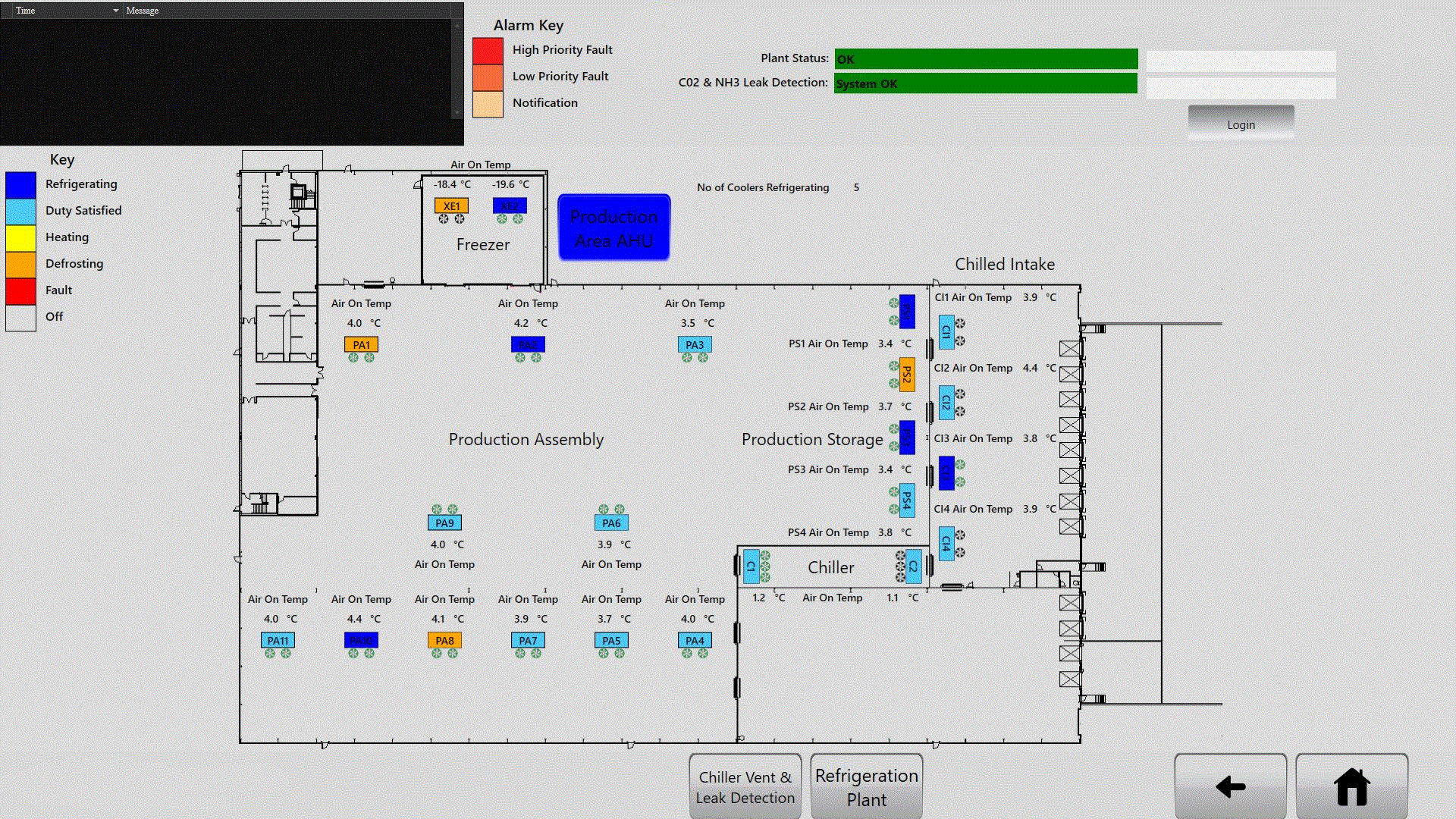
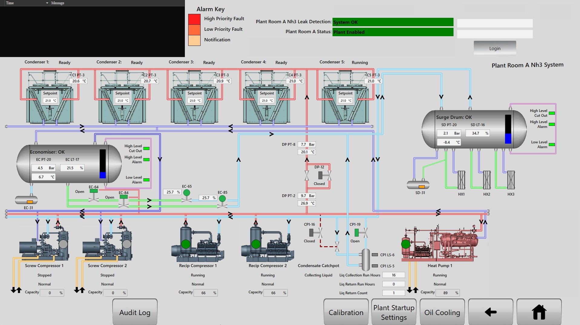
SCADA connectivity, remote diagnostics capability, and alarm management strategy are all panel design decisions. They require correct hardware selection, communication port provision, network segregation, and earthing practice - none of which can be added cleanly after the panel is built without introducing compromises.
Communication Architecture
Panels built on Siemens, Allen-Bradley, or RDM platforms each have defined communication protocols and network topologies. Specifying the correct PLC communication modules, ensuring adequate port provision for both operational network connections and engineering access, and designing the network architecture before the panel is manufactured determines what integration is possible - and at what cost - when the panel is connected to the wider automation estate.
A panel designed without Ethernet provision for SCADA connectivity, or with a single network port that must serve both operational and engineering traffic, creates constraints that are expensive to resolve after commissioning. These are not complex design decisions - they are decisions that must be made consciously rather than by omission.
Fault Diagnostics and Alarm Granularity
Fault response time is directly related to alarm granularity. A panel that presents a single 'system fault' output to the operator provides no actionable information. A panel designed with diagnostic inputs for each protection device state, individual motor run feedback, and structured fault logging in the PLC program reduces the time from fault occurrence to root cause identification substantially.
This is a programming decision as much as a hardware decision - which means the PLC program architecture must be specified alongside the panel hardware, not treated as a separate scope. Panels where the hardware and software are designed as an integrated system by the same team consistently outperform panels where electrical manufacture and PLC programming were separated between contractors.
Design integration eliminates accountability gaps
Same team: design, build, test, document — this principle eliminates the accountability gaps that arise when design, manufacture, and installation are divided between different contractors. When the panel manufacturer also writes the PLC program and commissions the installation, fault diagnostic architecture is consistent end to end, and there is a single point of accountability when something does not work as specified. JBB's in-house manufacturing and programming capability — applied across Siemens, Allen-Bradley, and RDM platforms since 1966 — is what makes this integration deliverable rather than aspirational. Learn more about the Control Panels & MCC Design service.
Specifying for Future Expansion Without a Future Redesign
The instinctive response to future expansion is to treat it as a future problem. It is not - by the time a production line extension or new machine connection requires panel modifications, the cost of retrofitting expansion capacity is substantially higher than the cost of designing it in from the start.
Expansion provisions that must be designed in at specification stage include:
- Busbar capacity — sized for foreseeable load growth, not just the connected load at commissioning. Uprating a busbar in a live panel is a significant and disruptive engineering exercise.
- Spare ways in distribution — empty MCB ways, blank terminals, and reserved cable entry positions cost almost nothing at manufacture and eliminate the need for panel extensions when additional circuits are required.
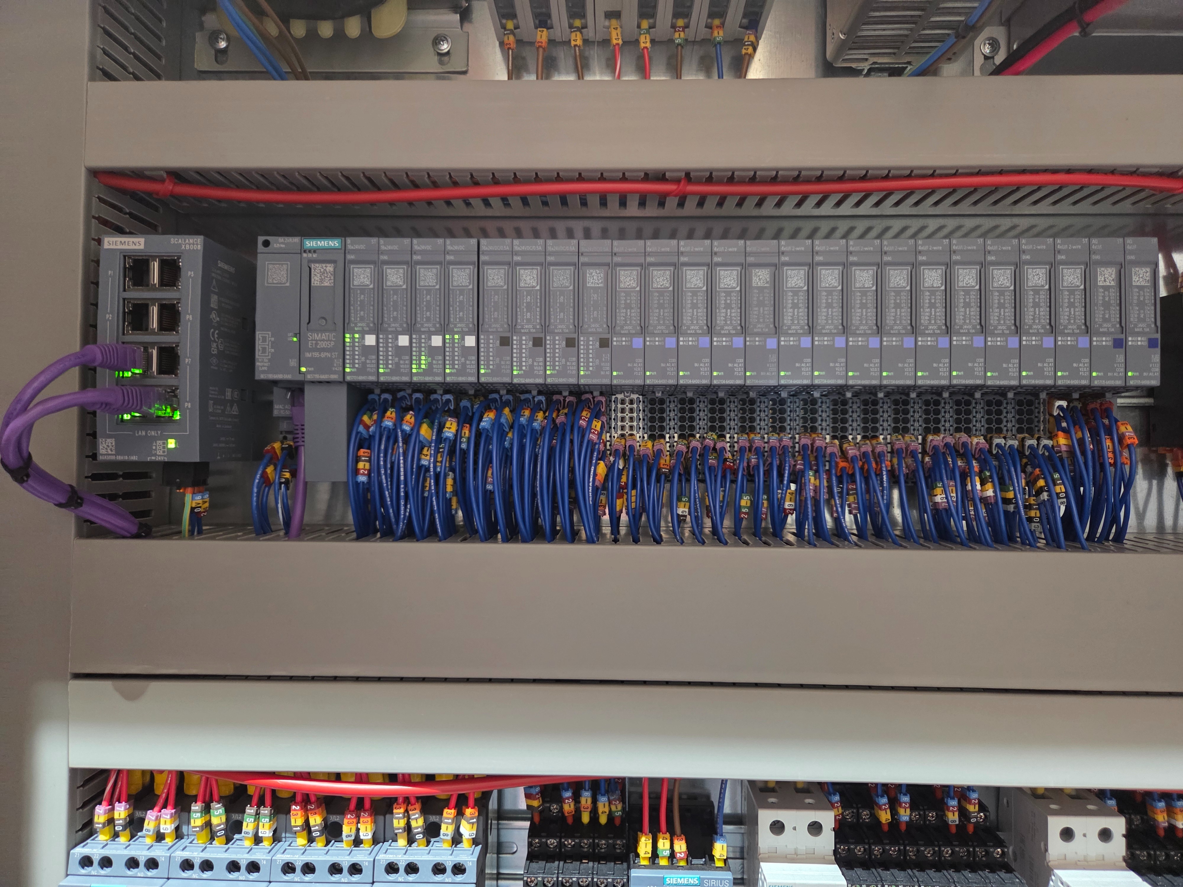
- I/O capacity — PLC I/O cards and communication modules specified with headroom beyond the immediate application, so additional sensors, drives, and interlocks can be connected without a processor or rack replacement.
- Cable management headroom — trunking and conduit at no more than 50–60% fill at commissioning, leaving physical capacity for additional conductors.
- Physical space within the enclosure — a panel built to exact current component count leaves no space for additions. A larger enclosure at build is consistently cheaper than a new panel or extension housing later.
The question to ask at specification stage is not 'what do we need now?' but 'what will we need in five years, and what would it cost to add it then versus now?' For most production facilities, the answer justifies meaningful headroom from the outset.
Build the expansion conversation into the brief
Ask your panel manufacturer to document their expansion provisions explicitly — reserved busbar capacity as a percentage of installed rating, I/O spare count, trunking fill levels, and spare ways. If a manufacturer cannot provide these figures, the panel has not been designed with expansion in mind. A NICEIC-approved contractor with in-house manufacturing capability should treat this as a standard deliverable, not an additional request.
The JBB PLC Control Panel Methodology
The JBB PLC Control Panel Methodology
Assess
JBB Electrical reviews your production environment, existing power distribution, and automation requirements to establish the correct fault protection levels, IP/NEMA ratings, busbar capacity, and BS EN 60204-1 compliance baseline before a component is specified - across Siemens, Allen-Bradley, and RDM platforms.
Modernise
Using EPLAN Electric P8, JBB designs the panel schematic, communication architecture, and PLC program structure as an integrated system - ensuring SCADA connectivity, alarm granularity, and diagnostic capability are built into the design rather than retrofitted after commissioning.
Protect
JBB's in-house manufacturing capability delivers panels with short-circuit rated assemblies, correctly coordinated protection devices, documented PE conductor sizing, and verified emergency stop architecture - all tested against BS EN 60204-1 requirements before the panel leaves the workshop.
Prevent
Every panel is specified with explicit expansion provisions - reserved busbar capacity, spare I/O ways, trunking headroom, and forward-compatible safety relay architecture - so foreseeable production changes do not require a panel redesign or extension housing.
Support
JBB Electrical delivers a complete documentation package with every panel: editable EPLAN schematics, test certificates, bill of materials, commissioning records, and version-controlled PLC configuration backups - the same documentation standard required by insurance inspectors and BS EN 60204-1 auditors, maintained as a living record through our Preventive Electrical Maintenance programmes.
Next Step: Request a Compliance & Breakdown Prevention Assessment
Next Step: Request a Compliance & Breakdown Prevention Assessment
A Compliance & Breakdown Prevention Assessment identifies the electrical, compliance, and breakdown risks affecting your operation, and sets out the engineering actions needed to reduce downtime, protect reliability, and keep your infrastructure defensibly compliant. Request a Compliance & Breakdown Prevention Assessment today to ensure your next PLC control panel is specified, built, and documented to a standard that delivers reliable performance for its full operational life.
Compliance & Breakdown Prevention Assessment