Programmable logic control systems are the decision-making layer of industrial operations. They read signals from field devices, execute control logic in real time, and drive outputs - motors, valves, actuators - based on that logic. Every second of production in a modern facility depends on this cycle running correctly.
The problem is that most facilities treat PLCs as fixed hardware rather than operational assets. Code goes undocumented. Platforms age past manufacturer support. Engineers who wrote the original logic move on. And the system that once ran cleanly starts producing intermittent faults nobody can confidently diagnose.
This guide covers how PLC control systems actually work, how they fail, and what good engineering looks like at every stage - from initial specification through integration and long-term maintainability.
What a Programmable Logic Controller Actually Does in an Industrial Environment
A PLC is a real-time industrial controller. It does not run on a standard operating system and it does not process tasks in the background - it executes a continuous scan cycle in a fixed sequence: read inputs, process logic, update outputs. That cycle repeats hundreds or thousands of times per second.
Cycle time matters operationally. A system with a slow scan cycle may miss a fast-moving process event - a pressure spike, a limit switch trigger, a safety signal. For most process control applications, cycle times in the range of 10 to 100 milliseconds are adequate. For motion control or safety-critical applications, tighter cycle times and dedicated safety PLCs are required.
Cycle Time and Safety
The PLC scan cycle directly affects system responsiveness. A safety interlock that depends on a digital input being detected within a specific time window will not function correctly if the scan cycle is too slow for the application. This is an engineering parameter - not a default setting to leave unchanged.
The practical consequence of this architecture is that PLCs are deterministic - they behave the same way every scan, given the same inputs. That determinism is precisely what makes them suited to industrial control. It also means that a fault in the logic, or a corrupted input signal, will produce consistent, repeatable incorrect behaviour - which is both a diagnostic advantage and a risk if the fault goes undetected.
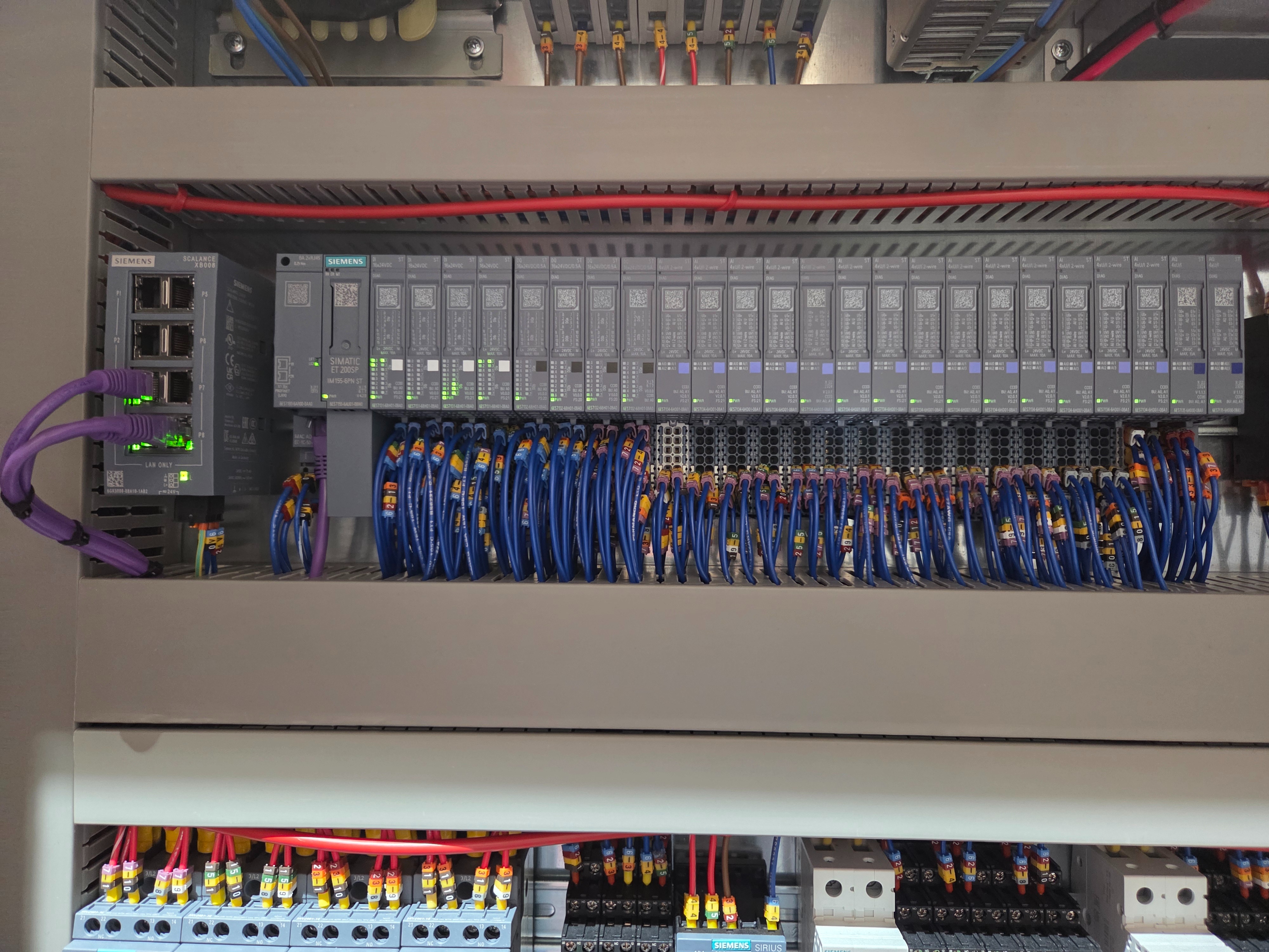
The Anatomy of a PLC Control System: Controllers, I/O, and the Control Panel
A PLC controller does not operate in isolation. It is one component within a wider system - and how that system is assembled determines its reliability, safety, and maintainability.
The core components of a PLC control system are:
- The CPU module - executes the control programme and manages communications
- I/O modules - digital and analogue, reading sensors and driving outputs
- Field devices - proximity switches, thermocouples, pressure transmitters, actuators
- Communication infrastructure - Profibus, Profinet, EtherNet/IP, or serial depending on platform and age
- The control panel enclosure - housing, protecting, and distributing power to all of the above
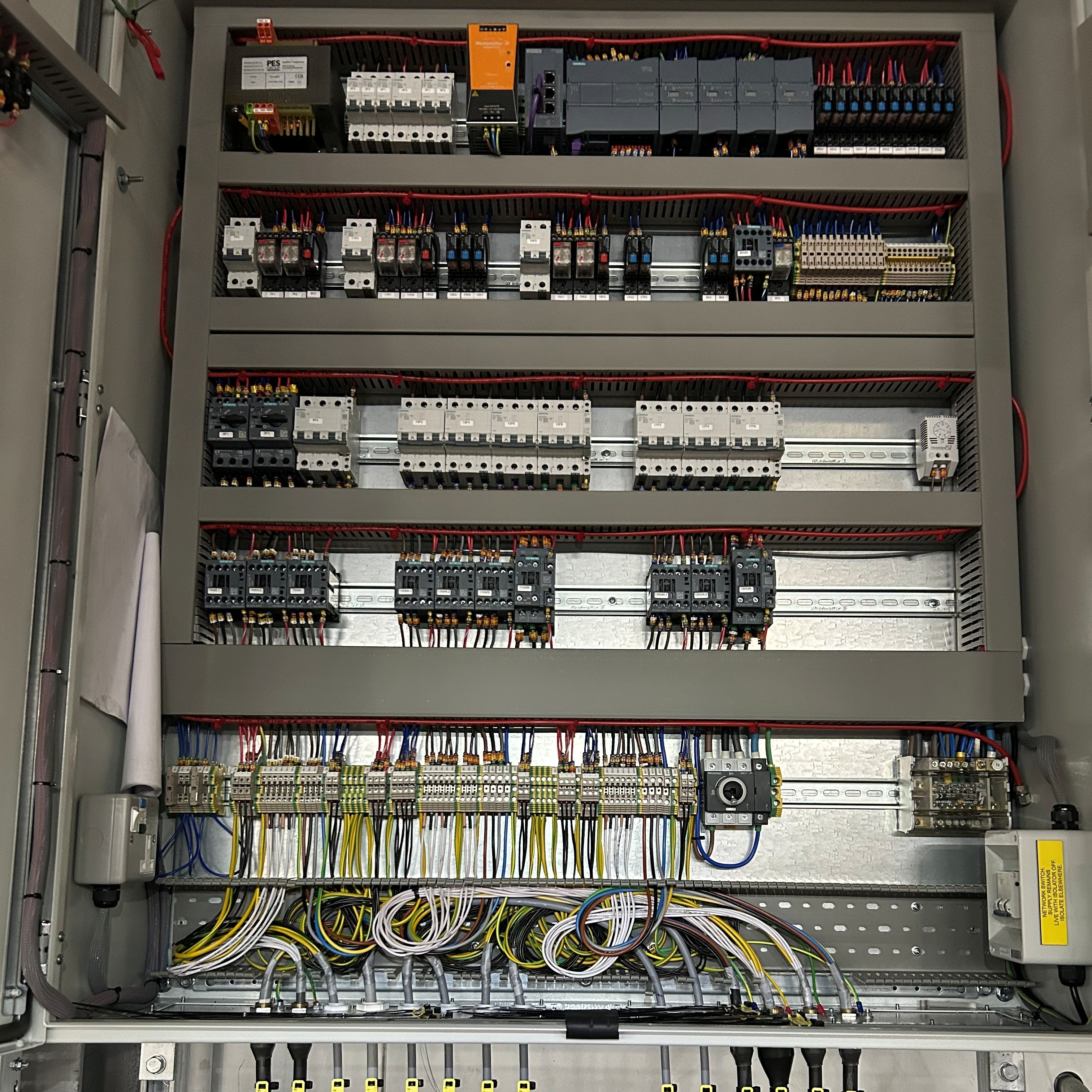
The control panel is not incidental. Its design directly affects whether the PLC system inside it can be safely maintained, safely modified, and reliably powered. A well-designed panel - with correctly rated protection devices, cable segregation, terminal identification, and spare I/O capacity - creates a platform for long-term operation. A poorly designed panel creates constraints from day one.
JBB Electrical's Control Panels & MCC Design service addresses panel design as an engineering discipline - not a box-building exercise. The same standards that govern the electrical installation (BS EN 60204-1 for safety of machinery) apply to the panel that houses the PLC, and compliance must be verified at commissioning.
How PLC Logic Works: Inputs, Outputs, and the Scan Cycle Explained
PLC logic is written in one of several IEC 61131-3 standard languages - Ladder Diagram, Function Block Diagram, Structured Text, or Instruction List. Ladder Diagram remains the most widely used in UK industrial installations, particularly on legacy systems. Structured Text is increasingly preferred for complex logic where procedural clarity matters.
The scan cycle works in three phases:
- Input scan - the processor reads the current state of all digital and analogue inputs and stores them in memory
- Programme execution - the control logic is processed against the stored input image, calculating output states
- Output scan - the calculated output states are written to the physical output modules, driving field devices
One practical implication: inputs are read once per scan. A signal that transitions and returns within a single scan may not be detected. For high-speed applications - detecting fast-moving product on a conveyor, for example - hardware interrupt inputs or high-speed counters are required, separate from the main scan cycle.
Safety Interlocks Are Not Optional
Safety interlocks embedded in PLC logic are mandatory protection mechanisms under BS EN 60204-1. They must be verified during commissioning with documented test evidence - and any code change that touches interlock logic requires re-verification. This is non-negotiable, regardless of how minor the modification appears.
PLC Platforms in Use: Siemens, Allen-Bradley, and Choosing the Right Controller
Platform choice is a long-term operational decision. The controller specified at installation will shape spare parts availability, programming toolchain, engineer familiarity, and support costs for the life of the equipment - often 15 to 25 years.
JBB Electrical programmes across Siemens, Allen-Bradley, and RDM platforms. Each has distinct characteristics that affect suitability for different applications:
- Siemens - TIA Portal as the programming environment, S7 series controllers widely deployed across process and manufacturing. Strong diagnostics, broad I/O range, well-supported in UK industrial supply chains.
- Allen-Bradley - Studio 5000 / RSLogix toolchain, ControlLogix and CompactLogix platforms common in packaging, material handling, and food processing. Strong motion control capability.
- RDM - deployed in specific refrigeration control and cold chain applications where integration with refrigeration plant is a primary requirement.
The decision made at specification - which platform, which CPU, which I/O architecture - cannot easily be reversed. A facility that has standardised on Siemens across 12 machines gains real operational benefit from that consistency: engineers know the toolchain, spares are interchangeable, and fault diagnosis follows familiar patterns. Introducing a different platform for a single machine creates a long-term maintenance anomaly.
Platform Obsolescence is a Planned Event
Manufacturer support lifecycles for PLC hardware are finite and published. An installed platform approaching end-of-life will see increasing lead times for replacement modules, reduced technical support, and eventual unavailability of spares. Identifying this trajectory early - and planning migration before failure - is substantially less costly than emergency replacement.
Where PLC Systems Fail - and What That Costs Operations
PLC failures rarely announce themselves cleanly. The more common pattern is gradual deterioration - intermittent faults, nuisance trips, unexplained stoppages that reset and recur. By the time a definitive failure occurs, there has typically been weeks or months of early-warning behaviour that went unaddressed.
Common failure modes in PLC control systems include:
- I/O module degradation - digital inputs reading incorrectly, analogue signals drifting, output channels failing to drive
- Power supply deterioration - causing processor resets or memory corruption
- Communication faults - network timeouts, lost device connections, CRC errors on serial links
- Battery failure - causing programme loss on older systems without flash-backed memory
- Logic faults introduced by undocumented code changes - where modifications made without version control create conflicts in execution
Illustrative Scenario - Intermittent Fault on a Packaging Line
Consider a packaging line PLC where operators are logging three to four unexplained stoppages per shift. The PLC fault log shows a recurring digital input fault on a proximity switch - the same input, the same fault code, resetting each time the operator clears the alarm. A site engineer inspecting the I/O module finds the input channel showing marginal voltage readings, consistent with a failing input card rather than a faulty sensor. The correct engineering response is to replace the I/O module during a planned maintenance window, verify the input signal levels post-replacement, and review whether the same module type is installed elsewhere on the line. Left unaddressed, the channel would progress to complete failure - turning a planned 30-minute module swap into an unplanned production stoppage of several hours while a replacement is sourced. Illustrative example based on representative JBB project work.
The cost of a PLC-related stoppage extends beyond the immediate downtime. Labour to diagnose, expedited component sourcing, potential product waste, and the reputational impact of missed delivery commitments all compound the original failure. A critical spares strategy - identifying the I/O modules, power supplies, and CPU types most likely to be needed - directly reduces recovery time when failure occurs.
Integrating PLCs with SCADA, HMI, and Wider Automation Infrastructure
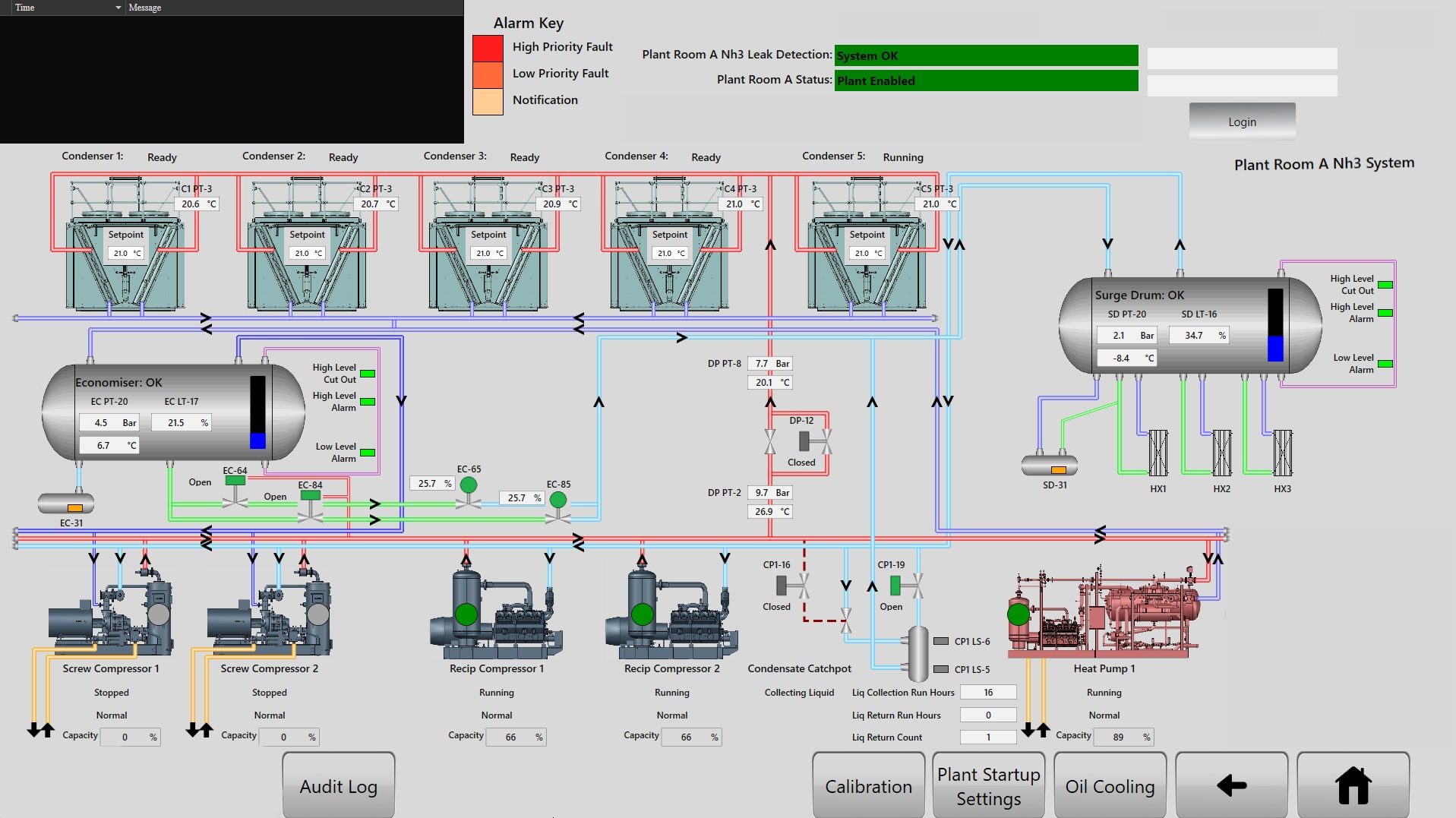
SCADA and HMI systems extend PLC visibility upward - from the controller to the operator interface and, in larger installations, to supervisory management systems. The PLC remains the control layer; SCADA and HMI add monitoring, alarm management, data logging, and operator interaction.
That integration introduces design considerations that affect both reliability and security:
- Communication protocol compatibility - the PLC must communicate with the SCADA or HMI platform over a supported network (Profinet, EtherNet/IP, Modbus TCP) without introducing latency that affects control performance
- Network segmentation - control networks should be isolated from corporate IT infrastructure to limit cybersecurity exposure
- Alarm rationalisation - HMI alarm lists that replicate every PLC diagnostic without prioritisation create alarm flood conditions, where operators cannot identify the root cause event
- Data integrity - process data logged through SCADA for regulatory or quality purposes must have a verified, auditable path from sensor to record
JBB Electrical's PLC programming work includes SCADA and HMI integration design - ensuring that the interface layer adds operator value without becoming a source of new failure modes. This is particularly relevant in refrigeration control applications, where process visibility across multiple plant items is operationally critical. See JBB's Refrigeration Control Systems service for how this integration is applied in cold chain environments.
What Good PLC Programming Looks Like: Documentation, Structure, and Maintainability
Poorly structured PLC code is a significant operational risk - not just a quality issue. Code that is undocumented, monolithic, or written by a contractor who no longer supports the site creates a system that cannot be safely modified, diagnosed, or handed over to a new engineering team.
The characteristics of well-structured PLC programming are specific and auditable:
Indicators of Maintainable PLC Code
- Modular programme organisation - logic grouped by function (motor control, sequencing, safety, alarms) rather than written as a single continuous routine
- Consistent naming conventions - I/O tags, internal variables, and programme blocks named to reflect the physical or functional element they represent
- Inline commentary - key logic decisions and interlock conditions explained in comments within the code, not in a separate document that may not be kept current
- Fault detection routines - active monitoring of communication health, I/O module status, and process value ranges, with structured alarm outputs
- Version control - programme versions numbered and dated, with a change log recording what was modified, by whom, and why
- Commissioning test documentation - records showing that all safety interlocks and critical sequences were tested against defined pass criteria
The Maintainability Test
A practical measure of whether PLC code is a managed asset or a liability: could a competent engineer who has never seen the system identify which logic controls which physical function, trace an interlock through the programme, and make a targeted modification without introducing unintended consequences - all within a reasonable time? If the answer is no, the code cannot be safely modified as process requirements change or key personnel leave. Structured programme organisation, consistent naming, and inline commentary are what make this test passable.
JBB Electrical structures every programme to these standards - code is written for long-term maintainability with modular design that allows future modifications to be made safely, without unintended consequences to other parts of the programme. Documentation is delivered as part of the project, not treated as optional.
The Single-Contractor Dependency
A facility that cannot safely modify its PLC programme without the original contractor is operationally vulnerable. If that contractor is unavailable, the system cannot be adapted to process changes, new equipment, or regulatory requirements without first reverse-engineering undocumented code. This is a foreseeable risk - and it is preventable through structured programming and proper handover documentation from the outset.
When to Upgrade, Reprogramme, or Replace Your PLC Control System
The decision between upgrading, reprogramming, and full replacement depends on a structured assessment of the current system - not a gut feeling about age. Some 20-year-old systems running on current hardware with well-documented code are in better shape than five-year-old systems that have been modified without version control.
The triggers that indicate a system needs intervention are:
- Hardware approaching or past manufacturer end-of-life - spare modules unavailable or on extended lead time
- Recurring faults that cannot be reliably diagnosed from existing documentation
- Process requirements that the current system cannot accommodate without significant workarounds
- Code that cannot be safely modified because it is undocumented, monolithic, or the original author is unavailable
- Safety interlock verification that cannot be demonstrated - either because documentation is missing or because commissioning test records do not exist
Reprogramming - rewriting control logic on the existing hardware platform, with improved structure and documentation - is often the right intervention when hardware is still supported but code quality has become the limiting factor. Platform migration - moving from an end-of-life controller to a current equivalent - is appropriate when hardware supportability is the primary concern. Full replacement addresses both simultaneously, typically during a planned shutdown.
JBB Electrical's preventive electrical maintenance programme includes PLC system condition assessment - reviewing hardware status, programme structure, documentation completeness, and platform support lifecycle - to give operations teams a clear picture of where their systems sit and what the timeline for intervention should be.
The JBB Programmable Logic Control Systems Methodology
The JBB Programmable Logic Control Systems Methodology
Assess
JBB Electrical engineers conduct a structured review of the existing PLC control system - auditing hardware platform and support lifecycle, inspecting programme structure and documentation completeness, verifying safety interlock records against BS EN 60204-1 requirements, and identifying I/O module condition and communication network health.
Modernise
Where hardware is approaching end-of-life or code quality has become a maintenance liability, JBB Electrical delivers platform migration or programme restructuring - rewriting control logic in a modular, documented format across Siemens, Allen-Bradley, or RDM platforms using EPLAN Electric P8 for panel documentation, and integrating SCADA and HMI layers where operator visibility is required.
Protect
Every JBB Electrical PLC programme is built with structured fault detection routines, verified safety interlocks, and alarm management designed to surface real faults clearly - ensuring that protection mechanisms function as designed and that code changes cannot inadvertently disable interlock logic.
Prevent
JBB Electrical's Compliance & Breakdown Prevention Assessment identifies the PLC-specific risks - undocumented code, obsolete I/O modules, unverified safety interlocks, and communication faults - before they produce unplanned stoppages, and establishes a prioritised action plan with defined timelines.
Support
As a NICEIC-approved contractor with a continuous operating history since 1966, JBB Electrical provides ongoing support across the full PLC control system - programme backups, version-controlled change management, spares planning for critical I/O and CPU modules, and engineering response when faults occur - with the same team that designed and built the system maintaining continuity of knowledge.
Next Step: Request a Compliance & Breakdown Prevention Assessment
Next Step: Request a Compliance & Breakdown Prevention Assessment
A Compliance & Breakdown Prevention Assessment identifies the electrical, compliance, and breakdown risks affecting your operation, and sets out the engineering actions needed to reduce downtime, protect reliability, and keep your infrastructure defensibly compliant. Request a Compliance & Breakdown Prevention Assessment today to get a clear, prioritised view of your PLC control system's condition - hardware supportability, programme quality, safety interlock status, and the actions needed to keep your automation infrastructure reliable and maintainable.
Compliance & Breakdown Prevention Assessment