The design decisions made when engineering a PLC control panel rarely become visible during commissioning. They surface months or years later - when a fault takes days to diagnose because the software has no structured naming convention, when a component fails and the replacement is discontinued, or when a safety interlock that was never properly integrated allows a hazardous condition to develop.
For facilities managers, operations directors, and engineers responsible for industrial automation, understanding what separates a well-engineered panel from a liability is not a technical exercise - it is a risk management decision. This article sets out the specific design disciplines that determine whether a PLC control panel supports long-term operational reliability or creates recurring cost, compliance gaps, and downtime.
Why PLC Control Panel Design Decisions Have Long-Term Consequences
A poorly specified panel can pass its initial inspection and still be fundamentally wrong. Component choices that ignore lifecycle data, software written without structure or documentation, safety systems bolted on rather than designed in - none of these failures are obvious at handover. They compound quietly until a breakdown, an audit, or a modification project forces them into the open.
The financial case for getting the design right is straightforward. Modifications to a poorly documented panel cost substantially more than modifications to a well-documented one. Fault-finding in unstructured PLC control software takes significantly longer than in modular, named code. And a panel that was never built to accommodate expansion will need partial or complete redesign when operational requirements change.
Design decisions compound over time
Every shortcut taken during design - whether in platform selection, software architecture, or documentation - creates a cost that grows with every year the panel remains in service. The correct time to address these decisions is before manufacture begins.
Hardware Selection: Choosing the Right PLC Platform and Components
Hardware platform selection is not primarily a technical question - it is a strategic one. The choice of PLC platform affects spares availability, support lifecycle, the availability of programming expertise, and the cost of every future modification. These factors must be assessed at the design stage, not after installation.
JBB Electrical works across Siemens, Allen-Bradley, and RDM platforms, and the correct platform selection depends on the specific operational environment, the existing automation estate, and the client's engineering resource. A food processing facility already running Allen-Bradley throughout its production lines has strong reasons to standardise - reducing training requirements, spares inventory, and integration complexity. A greenfield pharmaceutical installation may prioritise a platform with a longer published product lifecycle and stronger regional support.
Published product lifecycle - confirm the platform's expected support duration from the manufacturer before specifying
Spares availability - identify whether critical modules are stocked domestically and what lead times apply for end-of-life components
Obsolescence planning - select components with known lifecycle trajectories and document critical spares requirements at design stage
Site standardisation - align with the facility's existing platform where practical to reduce training, tooling, and support overhead
Expansion headroom - specify I/O capacity with realistic growth requirements factored in, not just current point count
Avoiding platform lock-in without a strategy is equally important. Selecting an obscure platform to reduce initial cost creates significant risk when the facility needs a modification and the original programmer is unavailable. Platforms with broad industry adoption and established training pathways reduce this exposure.
Why Unstructured PLC Code Multiplies Fault-Finding Time
Unstructured PLC code is one of the most common sources of extended fault-finding time in industrial facilities. When control logic is written without naming conventions, without modular structure, and without inline commentary, diagnosing a fault requires an engineer to reconstruct the original programmer's intent from first principles - under operational pressure.
PLC control software should be written with long-term maintainability as a primary design objective. This means structured, modular code with clear naming conventions for every tag, rung, and function block. It means version control — so that every change is documented, dated, and reversible, creating a traceable record that satisfies compliance auditors and protects any engineer working on the panel in future. And it means alarm management logic that distinguishes genuine fault conditions from nuisance trips, reducing operator workload and preventing alarm flooding during fault states.
Version control is good practice
Every change made to PLC control software must be recorded with a version number, date, and description of what was modified and why. Without this record, an engineer investigating a fault cannot determine whether they are looking at the original commissioned logic or a subsequent modification. Where modifications have been made without version control, the installed software cannot be safely changed — because the baseline is unknown. Version-controlled software is a compliance deliverable, not a programming preference.
Code that the next engineer can read
Well-structured PLC software uses consistent tag naming, modular function blocks, and clear inline commentary. The test is straightforward: can a competent engineer who did not write the code diagnose a fault and make a modification safely, without needing to contact the original author?
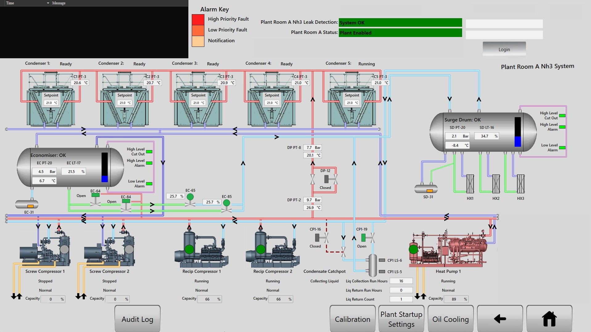
Software architecture should also include data logging and SCADA/HMI integration where relevant - not as a bolt-on feature, but as a designed element of the control architecture. Process data that is captured systematically provides the basis for predictive maintenance decisions and supports compliance reporting in regulated environments.
Safety Integration: Protection Schemes, Interlocks, and Fault Detection
Safety interlocks and fault detection logic must be designed into the control architecture from the outset. Adding them retrospectively is technically possible, but the result is typically less reliable, harder to document, and more difficult to verify - because the underlying control structure was not designed to accommodate them.
BS EN 60204-1, which covers the electrical equipment of machines, sets requirements relevant to emergency stop integration, overload protection, and other aspects of machinery electrical equipment. Compliance must be verified and documented, not assumed. Where safety-related control functions are required, BS EN ISO 13849-1 and/or EN 62061 may also apply, depending on the machinery and safety architecture.
Emergency stop circuits must de-energise correctly and achieve the required stop category. Overload protection must be sized correctly for the connected loads and verified under test conditions. Where a Performance Level (PL) or Safety Integrity Level (SIL) is required, the relevant safety functions must be validated against the required level.
Stop category achievement must be verified, not assumed
BS EN 60204-1 defines stop categories 0, 1, and 2, each with distinct requirements for how power is removed from driven machinery. A Category 0 stop removes power immediately; a Category 1 stop allows controlled deceleration before power removal. The correct stop category for each drive and machine axis must be determined at design stage — and the emergency stop circuit must be verified to achieve it under test conditions. A stop circuit that achieves the wrong category, or that has never been tested, is not a compliant safety function.
Emergency stop integration - verified to achieve the correct stop category per BS EN 60204-1, with function tested and documented
Overload protection - correctly sized for connected loads, with settings recorded in the panel documentation
Fault detection logic - designed to identify specific fault conditions and generate targeted alarms, not generic error states
Safety validation - where applicable, safety-related control functions should be validated against the required Performance Level (PL) or Safety Integrity Level (SIL)
Safety relay integration - where safety functions are required, dedicated safety relays or safety PLCs should be specified rather than relying on standard control logic
Alarm management - structured to distinguish fault priorities and prevent alarm flooding that causes operators to ignore genuine hazard signals
Safety logic added retrospectively carries higher risk
When interlocks and protection schemes are designed in from the start, they can be verified systematically. When they are added after the fact, the interaction between new and existing logic is harder to test - and the gaps are less visible until a fault state exposes them.
Panel Layout, Thermal Management, and Environmental Ratings
The physical design of a control panel directly affects its operating temperature, maintenance access, and regulatory compliance. These are engineering decisions with measurable consequences - not aesthetic preferences.
Component spacing must allow adequate airflow and access for maintenance without requiring partial disassembly of adjacent equipment. Cable segregation between power and signal cables is a fundamental requirement - running them in parallel over significant distances introduces interference that can cause intermittent faults that are notoriously difficult to diagnose. The IP rating selected for the enclosure must reflect the actual operating environment, including wash-down exposure in food processing, dust ingress in manufacturing, and chemical exposure in pharmaceutical or cold storage environments.
Illustrative example - representative of the engineering pattern, not a documented JBB project
Consider a food manufacturing facility where a control panel was originally specified with an IP54 rating but installed in a zone subject to regular high-pressure wash-down. Over time, moisture ingress causes intermittent faults on signal terminals - faults that appear random because they occur only after cleaning cycles. A review of the installation would identify the enclosure rating mismatch, the absence of sealed cable entry points, and condensation evidence on the backplate. The correct engineering response is to upgrade the enclosure to IP65 or IP66, install sealed cable glands, and add a thermostatically controlled enclosure heater to manage condensation - preventing repeated unplanned downtime from a design oversight addressable at specification stage.
Thermal management deserves specific attention. PLCs, drives, and power supplies generate heat, and enclosures that are correctly rated for their environment may still operate at elevated internal temperatures if ventilation is inadequate. Thermal calculations should be performed at design stage, with fan units, heat exchangers, or air conditioning specified where the heat load exceeds passive dissipation capacity.
Does Your Panel Documentation Reflect the As-Built Configuration?
A panel without comprehensive documentation is an operational liability. Maintenance engineers cannot work safely and efficiently without accurate schematic drawings. Compliance auditors cannot verify the installation without test certificates. Fault-finding without an I/O schedule is slower and riskier. And a software modification without version-controlled code documentation risks introducing new faults while fixing existing ones.
For machine control panels, documentation requirements are typically shaped by BS EN 60204-1, the UK Supply of Machinery (Safety) Regulations and, where applicable, BS EN 61439-1/2 for low-voltage switchgear and controlgear assemblies. Where machinery is supplied under UKCA requirements, the relevant technical documentation must also be maintained as part of demonstrating conformity.
Minimum documentation package for a well-designed control panel
Schematic drawings - accurate to the as-built configuration, not the original design intent
I/O schedule - complete list of all inputs and outputs with descriptions, addresses, and signal types
Software documentation - structured code with naming conventions, version history, and functional description
Test certificates - FAT and SAT results, insulation resistance tests, and protection verification records
Component data sheets and firmware versions - for all critical components including PLC modules, drives, and safety relays
Maintenance schedule - recommended inspection intervals, calibration requirements, and critical spares list
BS 7671 sets documentation requirements for electrical installations, and compliance documentation must be current and accessible. Panels that were installed years ago and never had their documentation updated to reflect modifications present a significant audit and safety risk - the installed reality no longer matches the record, and any engineer working on the panel is working from inaccurate information.
Testing and Commissioning: Verifying the Design Before It Goes Live
Factory Acceptance Testing (FAT) and Site Acceptance Testing (SAT) are the mechanisms by which the design is verified against the specification - before and after installation. Skipping or abbreviating either creates a situation where design errors are discovered during production, at maximum operational cost.
FAT is conducted at the manufacturer's premises before the panel is shipped. It verifies that control logic operates correctly, that safety interlocks function as designed, and that the panel meets its electrical specification. Every test result is recorded. Issues identified during FAT are resolved before the panel leaves the workshop - not during commissioning, where the time and cost of rework are substantially higher.
SAT follows installation and confirms that the panel operates correctly in its installed environment, integrated with the connected machinery and process systems. Site conditions - cable lengths, earthing arrangements, supply quality, and ambient temperature - can all affect performance in ways that were not apparent during FAT. Both test stages are documented, and the test certificates form part of the panel's permanent compliance record.
FAT and SAT records are permanent compliance documents
Factory Acceptance Testing and Site Acceptance Testing records are not internal project documents — they are part of the panel's permanent compliance file. They demonstrate that specific safety functions were verified at a defined point in time, against a defined specification, by a named party. If the panel is modified years later, the original test records establish the baseline against which the modified system must be re-verified. Facilities that cannot produce FAT and SAT records for their installed panels cannot demonstrate compliance for those panels — and cannot safely characterise what any future modification may affect.
Common Design Mistakes Industrial Facilities Should Avoid
The same design failures appear repeatedly across industrial facilities, regardless of sector. Understanding them is the first step to specifying against them.
Specifying on price rather than lifecycle cost — the cheapest panel at purchase often becomes the most expensive in service, when spares are unavailable, modifications require reverse-engineering, and faults take longer to diagnose
Accepting undocumented or poorly documented panels — documentation gaps become operational hazards the first time a modification or fault-finding exercise is required
Allowing safety interlocks to be added retrospectively — consistently more expensive and less reliable than designing them in from the start
Ignoring obsolescence at design stage — specifying components already in decline creates a spares crisis within the panel's expected service life
Undersizing the enclosure — inadequate space for cable management, future I/O expansion, and maintenance access is difficult to rectify after installation
Commissioning without formal FAT and SAT — design errors discovered during production are resolved at the highest possible cost
The right time to address these issues
Every one of the design mistakes above is straightforward to address at specification and design stage. Once the panel is built, installed, and integrated into a production process, the cost of correction rises substantially - and the operational disruption required to implement changes increases with every year in service.
The JBB PLC Control Panel Design Methodology
The JBB PLC Control Panel Design Methodology
Assess
We review the operational environment, existing automation estate, and electrical infrastructure to determine the correct PLC platform - from Siemens, Allen-Bradley, or RDM - and identify any legacy documentation gaps, obsolescence risks, or BS EN 60204-1 compliance issues before design begins.
Modernise
Using EPLAN Electric P8 for schematic design, we engineer the control panel to current standards - specifying components with confirmed lifecycle trajectories, designing modular PLC control software with structured naming conventions and version control, and integrating safety interlocks and fault detection logic into the core control architecture.
Protect
We verify emergency stop integration, overload protection settings, and alarm management logic against BS EN 60204-1 requirements, and ensure the enclosure IP rating, cable segregation, and thermal management provisions are correctly specified for the operating environment - with all test results documented as part of the panel's compliance record.
Prevent
As a NICEIC-approved contractor, we conduct Factory Acceptance Testing before the panel leaves our in-house manufacturing facility, and Site Acceptance Testing after installation - capturing test certificates, I/O schedules, software documentation, and maintenance schedules that allow future engineers to diagnose faults and make modifications safely.
Support
JBB Electrical provides ongoing preventive electrical maintenance and compliance assessments, including critical spares strategy to address component obsolescence - ensuring that the panel continues to meet its operational and regulatory requirements throughout its service life, not just at the point of commissioning.
JBB Electrical has designed, manufactured, and commissioned PLC control panels since 1966, with in-house capability covering schematic design, component sourcing, assembly, testing, and certification. The same team: design, build, test, document — eliminating the accountability gaps that arise when design, manufacture, and installation are divided between different contractors. For facilities looking to understand what their existing panels contain and where the risks lie, a Compliance & Breakdown Prevention Assessment provides the structured starting point.
Next Step: Request a Compliance & Breakdown Prevention Assessment
Next Step: Request a Compliance & Breakdown Prevention Assessment
A Compliance & Breakdown Prevention Assessment identifies the electrical, compliance, and breakdown risks affecting your operation, and sets out the engineering actions needed to reduce downtime, protect reliability, and keep your infrastructure defensibly compliant. Request a Compliance & Breakdown Prevention Assessment today to ensure your PLC control panels are designed, documented, and maintained to the standard that industrial operations require.
Compliance & Breakdown Prevention Assessment