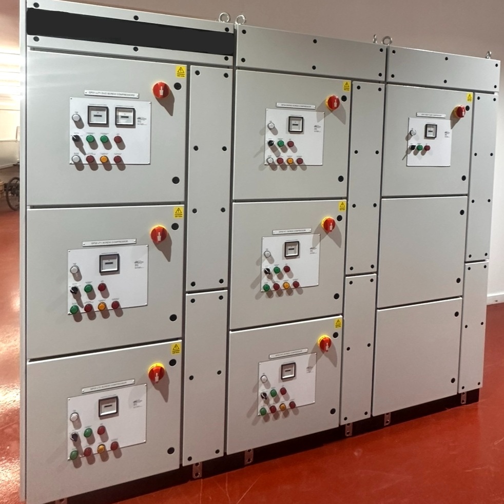

Specifying the wrong type of control panel in electrical infrastructure is one of the most common - and costly - decisions a facilities team can make. An under-rated panel, a panel delivered without adequate documentation, presents significant difficulties in maintenance, future modification and demonstrating compliance during inspections.
This guide defines the principal panel types used in industrial and commercial settings, explains the engineering distinction between each, and sets out the specification decisions that determine whether a panel serves your facility reliably for its full serviceable life.
What Is an Electrical Control Panel and What Does It Do?
An electrical control panel is an enclosure that houses the switching, protection, and control equipment needed to distribute power and manage electrical loads safely. It sits between the incoming supply and the equipment it serves - receiving power, distributing it and providing the protection and control interfaces that allow operators and automation systems to manage those circuits.
In a basic commercial building, that function is straightforward: a distribution board routes power to lighting and small power circuits, with overcurrent protection on each way. In an industrial facility, the same principle scales to a far more complex architecture - Motor Control Centres managing dozens of driven loads, PLC panels executing process logic, and power factor correction equipment protecting sensitive machinery from voltage instability.
Control Panel - Core Function
A control panel does three things: it distributes power safely to downstream equipment, it provides protection against fault conditions, and it gives operators or automation systems the means to control electrical loads. Panel type is determined by which of these functions takes precedence in a given application.
Understanding this core function is essential before categorising types. The engineering distinction between panel types is not primarily cosmetic - it reflects primary duty of the equipment and the required level of protection and control.
The Main Types of Electrical Control Panel Explained
Industrial and commercial facilities typically draw on six principal panel types, each with a distinct engineering purpose. Selecting an unsuitable panel type at the design stage is one of the most common causes of future operational and maintenance issues.
Mains LV Distribution Boards
A Main Distribution Board receives the incoming supply from the transformer or DNO connection and distributes it to sub-circuits and downstream panels. It carries the highest fault-level exposure on site and must be rated accordingly - both in terms of short-circuit capacity and the interrupting rating of its protection devices.
MDBs are typically specified with moulded case circuit breakers (MCCBs), SPDs, or air circuit breakers (ACBs) at the incomer, providing discrimination with downstream devices. Bus bar sizing, cable entry arrangements, and metering provisions are all engineering decisions made at MDB specification stage - changing them later is rarely straightforward.
Key MDB Specification Decisions
Four decisions made at MDB specification stage are difficult to reverse after installation: incomer protection device type and interrupting rating (ACB or MCCB, matched to the prospective fault current); bus bar cross-section (sized for continuous current and fault withstand duration); metering and sub-metering provision (required for energy management and tariff compliance); and cable entry arrangement (top or bottom entry, cable size, and number of ways must be defined before the enclosure is manufactured). Changing any of these after installation typically requires the panel to be de-energised, partially rebuilt, and future-proofed for extra load capability.
Motor Control Centres (MCCs)
A Motor Control Centre (MCC) is a dedicated panel assembly for starting, stopping, protecting, and reversing electric motors. In a food processing or manufacturing facility, the MCC is often the most operationally critical panel on site - controlling pumps, conveyors, compressors, fans, and process machinery.
Each motor is served by a dedicated functional unit within the MCC, typically comprising an isolator, motor circuit breaker, contactor, and overload relay. Modern MCCs also incorporate soft starters or variable speed drives (VSDs) where controlled acceleration, energy efficiency, or speed variation is required.
The engineering distinction that matters at specification stage is bus bar rating, fault level, and form of separation between functional units. IEC 61439 defines the four form factors (Form 1 through Form 4), each providing increasing segregation between components and functional units. A Form 4 MCC allows individual functional units to be maintained while adjacent units remain live - a significant operational advantage in facilities where planned shutdowns are difficult to arrange.
MCC vs Power Distribution Board — Engineering Distinction
An MCC and a Distribution Board (DB) both receive power from the Main Distribution Board (MDB) and distribute it downstream, but they are designed for fundamentally different purposes. An MCC is built specifically for motor control: each functional unit typically includes a motor circuit breaker, contactor, and overload relay rated for AC3 switching duty, with busbars designed to withstand the fault levels associated with motor inrush currents.
A Distribution Board, by contrast, is primarily intended to distribute power to downstream circuits using protective devices such as MCBs and RCDs. While a DB can supply motor circuits—often using Type C or Type D MCBs to accommodate motor starting currents—it does not provide the dedicated motor control functions of an MCC, such as start/stop control, contactors, or motor overload relays. Specifying a Distribution Board where an MCC is required, or vice versa, can result in a system that is difficult to maintain, lacks the necessary control and protection features, and cannot be expanded efficiently to meet future operational requirements.
PLC and Automation Control Panels
A PLC panel houses the programmable logic controller and associated I/O modules that execute process control logic. Unlike a distribution board or MCC, its primary function is not power switching - it is signal management and decision-making. Power distribution within a PLC panel is typically low-voltage DC for the control circuits, with the PLC itself receiving a clean 24V supply through a regulated power supply unit.
JBB Electrical designs and builds PLC panels across Siemens, Allen-Bradley, and RDM platforms, with SCADA/HMI integration where process visibility and remote monitoring are required. The component selection inside a PLC panel - terminal assembly, cable management, earthing arrangements, and surge protection - directly affects the reliability of the control system and its resilience to electrical noise from adjacent power circuits.
LV Distribution Boards
An LV Distribution Board operates downstream of the MDB, distributing power to a defined zone or process area. In a large facility, multiple PDBs serve different areas, each fed from the main distribution board and each providing localised circuit protection. PDBs are typically specified with miniature circuit breakers (MCBs), residual current devices (RCDs) or residual current circuit breakers with overcurrent protection (RCBO) at circuit level, and their fault level must be verified against the fault current at the point of supply.
Power Factor Correction Panels
Facilities with a high proportion of inductive loads - motors, transformers, welding equipment - typically draw reactive current that reduces the efficiency of the electrical supply and attracts penalty charges from the network operator. A power factor correction panel houses the capacitor banks and associated switching equipment needed to compensate for this reactive demand, improving power factor toward unity.
Specification of a power factor correction panel requires a site power quality assessment - installing correction capacity without understanding the harmonic content of the supply can cause capacitor failure and introduce new resonance problems. This is a common design error in facilities that specify correction panels on nameplate ratings alone.
Bespoke Process Control Panels
Bespoke process control panels are engineered to a specific operational brief—typically where standard panel configurations cannot accommodate the control logic, environmental conditions, or integration requirements of a particular process. Refrigeration control systems are a good example: the panel must manage compressor staging, variable speed drives (VSDs), defrost cycles, alarm outputs, and temperature monitoring interfaces within a single enclosure, often rated to IP54 or above for a cold and humid plant room environment.
JBB's Control Panel Design & Manufacture service covers bespoke process control panels from initial schematic design through to tested, certified, and documented delivery - with in-house manufacturing capability that eliminates the accountability gaps that arise when design, manufacture, and installation are divided between different contractors.
Key Components Inside an Industrial Control Panel
Component selection inside a control panel is not interchangeable between panel types. The duty, environment, and control architecture of each panel type drive different component requirements.
Circuit breakers (MCBs, MCCBs, ACBs): Provide overcurrent and short-circuit protection. Fault level must be verified against the available fault current at the point of connection - a device rated below the prospective fault current will not interrupt a fault safely.
Contactors: Electrically operated switching devices used to start and stop motors or switch high-current loads. AC3 duty rating applies to squirrel cage motor applications; AC1 for resistive loads. Incorrect duty selection causes premature contact wear.
Overload relays: Protect motors against sustained overcurrent. Electronic overload relays offer trip class selection, phase imbalance detection, and data logging capability that thermal bimetallics cannot provide.
Bus bars: Copper or aluminium conductors that carry the incoming supply across the panel. Bus bar cross-section must be sized for continuous current rating and fault withstand duration - undersized bus bars are a thermal risk in high-fault-level installations.
Terminal assembly: The interface between internal panel wiring and external field cables. Terminal block selection - including spring-cage versus screw-type, and whether current-rated test-disconnect terminals are required - varies significantly between MCC, PLC, and process control applications.
HMI interfaces: Touchscreen or pushbutton-based operator interfaces. In PLC panels with SCADA/HMI integration, the HMI specification must align with the PLC platform - Siemens panels typically pair with SIMATIC HMIs; Allen-Bradley panels with PanelView units.
Component Specification Risk
A control panel assembled from correctly specified individual components can still fail in service if the assembly does not account for thermal dissipation, cable segregation between power and control circuits, or adequate discrimination between protection devices. Component selection and panel engineering are not the same discipline.
How Panel Type Affects Compliance, Safety, and Maintainability
Two regulatory frameworks govern industrial control panel specification in the UK. Getting either wrong creates compliance exposure that surfaces - often at the worst possible moment - during an insurance inspection, a notifiable incident investigation, or a planned production audit.
BS EN 60204-1 applies to the electrical equipment of machines and governs how control panels associated with machinery are designed, built, and documented. It defines requirements for emergency stop functionality, protective separation of control and power circuits, marking, and the documentation that must accompany the panel - including circuit diagrams, component lists, and test records. A panel that lacks BS EN 60204-1 compliant documentation is not certifiable as part of a CE or UKCA-marked machine.
BS 7671 - the IET Wiring Regulations - governs the installation of the panel within the electrical system. It defines requirements for overcurrent protection, earthing and bonding, identification of conductors, and the verification and certification of the completed installation. A panel that is compliant with BS EN 60204-1 at manufacture may still create a BS 7671 non-compliance if it is installed without a proper inspection and test programme.
Regulatory Framework — BS EN 60204-1 and BS 7671
Two frameworks govern industrial control panel compliance in the UK. BS EN 60204-1 applies to panels associated with machinery: it governs design, documentation, emergency stop functionality, and the protective separation of control and power circuits — and requires that compliant documentation accompany the panel at delivery. BS 7671 governs the installation of the panel within the electrical system: overcurrent protection, earthing and bonding, conductor identification, and the inspection and test programme that certifies the completed installation. A panel can comply with BS EN 60204-1 at manufacture and still create a BS 7671 non-compliance if it is installed without a proper test and verification regime. Both frameworks apply simultaneously, and neither substitutes for the other.
Safe Isolation and Maintainability
Panel type directly affects how safely and quickly maintenance can be carried out. An MCC with Form 4 separation allows single motor circuit maintenance without a full panel shutdown. A Distribution Board without clearly labelled circuit schedules and test records creates a genuine hazard during fault-finding - the engineer cannot confidently identify which protective device covers which circuit. Maintainability must be engineered in at specification stage, not addressed retrospectively.
IP rating is a specification decision with direct safety consequence. A panel rated IP20 - suitable for a clean, dry switchroom - installed in a washdown area or outdoor enclosure will suffer accelerated insulation deterioration, contact corrosion, and ultimately represent a shock risk. IP rating must be specified against the actual environmental conditions of the installation location, not the conditions of the ideal location.
Matching Panel Type to Your Operational Requirements
The wrong panel type creates problems that compound over time. An MCC with insufficient bus bar capacity to support additional motor loads, a PLC panel with no spare I/O capacity for future sensors, or a distribution board without sub-metering provision for energy management - each of these is a specification decision that becomes a constraint on every future operational change.
Matching panel type to operational requirements involves asking four questions at specification stage:
What is the primary function of this panel? Power distribution, motor control, process automation, power quality correction, or a combination - the answer determines the panel type and the regulatory framework that applies.
What is the fault level at the point of supply? Every protection device, bus bar, and cable in the panel must be rated to withstand and interrupt the available fault current. This requires a fault level calculation, not an estimate.
What are the environmental conditions? Temperature range, humidity, presence of dust, corrosive atmosphere, or washdown exposure - each drives IP rating, enclosure material, and internal component selection.
What are the future load and expansion requirements? A panel specified only for today’s load profile, with no allowance for expansion, may require replacement rather than modification when operational demands increase. Allowing spare ways, spare I/O capacity, and sufficient electrical capacity for future load growth during the design stage is typically far more cost-effective than building to minimum current requirements and upgrading the system later. Specifying for a realistic 10-year load growth profile helps ensure the panel remains adaptable, maintainable, and suitable for future operational needs.
Illustrative Scenario - MCC Misspecification
Consider a food manufacturing facility where a new processing line requires the addition of six motor starters to an existing MCC. If the original MCC was specified to Form 2 separation with no spare bus bar capacity, the addition cannot be accommodated safely within the existing enclosure. The engineering consequence is either a new standalone MCC - with all the associated cabling, installation, and commissioning costs - or a complete MCC replacement. Had the original specification included Form 4 separation and 25% spare bus bar capacity, the expansion would have been a straightforward functional unit addition. Illustrative example based on representative JBB project work.
For facilities where refrigeration, cold storage, or temperature-critical processes are involved, panel selection also needs to account for the control and monitoring interfaces required - connecting the panel type decision to wider temperature assurance and refrigeration control requirements.
What to Expect from a Bespoke Control Panel Specification
A properly engineered bespoke control panel does not begin with component selection. It begins with a detailed operational brief - understanding what the panel must do, in what environment, to what regulatory standard, and how it integrates with the wider electrical and automation infrastructure.
JBB Electrical has been delivering bespoke control panels since 1966 and operates as a NICEIC-approved contractor. The specification process is structured around defined engineering deliverables, not a catalogue selection exercise.
The JBB Control Panel Specification Methodology
The JBB Control Panel Specification Methodology
Assess
We review the operational brief, fault level data, environmental conditions, and existing electrical installation drawings to establish the correct panel type, bus bar rating, IP classification, and regulatory framework - whether BS EN 60204-1 for machine-associated panels or BS 7671 for distribution and power control applications.
Modernise
Where an existing panel is being replaced or upgraded, we use EPLAN Electric P8 to produce updated schematics that reflect current component specifications, Siemens or Allen-Bradley platform requirements, and any changes to SCADA/HMI integration points - ensuring the new design eliminates the limitations of the original installation.
Protect
Protection coordination is verified across all devices - from the incomer ACB or MCCB through to individual motor circuit breakers and overload relays - confirming discrimination at the available fault level and ensuring that a fault on any circuit clears without tripping upstream devices or exposing bus bars to sustained fault current.
Prevent
In-house manufacturing capability allows us to build expansion capacity, spare I/O capacity in PLC panels, and future cable entry provisions into the panel at manufacture - preventing the misspecification scenarios where a panel sized for today's load profile cannot accommodate the next operational change without replacement.
Support
Every panel delivered under JBB's Control Panel Design & Manufacture service includes full circuit documentation, testing certificates, component lists, and a maintenance schedule - giving the facilities team and any future maintenance contractor the information needed to work on the panel safely and keep it compliant across its operational life.
The deliverables from a properly engineered specification process should include: schematic drawings produced in a recognised engineering tool such as EPLAN Electric P8; a fully documented bill of materials with component datasheets; factory acceptance test records; installation and commissioning documentation; and an operation and maintenance manual that is specific to the panel as built - not a generic manufacturer's handbook.
Panels that arrive on site without this documentation package create an immediate compliance gap. BS EN 60204-1 requires that the documentation accompany the panel at delivery. A panel without documentation cannot be safely maintained, cannot be confidently modified, and cannot demonstrate compliance during an inspection. Same team: design, build, test, document - eliminating the accountability gaps that arise when design, manufacture, and installation are divided between different contractors.
What to Check at Panel Delivery
Before accepting delivery of any control panel, confirm that the following are included: circuit diagrams as-built (not as-designed), a factory test certificate signed by the responsible engineer, a component schedule identifying every device by make, model, and rating, and a clear maintenance access drawing showing isolation points. If any of these are missing, the panel is not ready for commissioning regardless of how it appears physically.
For facilities planning new electrical installations or integrating new panel assemblies into existing infrastructure, the panel specification process connects directly to the wider installation design - cable sizing, containment routes, switchroom layout, and coordination with mechanical trades. Managing these interfaces through a single engineering team, rather than across separate contractors, is consistently the most reliable way to ensure the installation passes certification first time.
Next Step: Request a Compliance & Breakdown Prevention Assessment
Next Step: Request a Compliance & Breakdown Prevention Assessment
A Compliance & Breakdown Prevention Assessment identifies the electrical, compliance, and breakdown risks affecting your operation, and sets out the engineering actions needed to reduce downtime, protect reliability, and keep your infrastructure defensibly compliant. Request a Compliance & Breakdown Prevention Assessment today to ensure your control panel types are correctly specified, documented, and maintained for the demands your facility places on them.
Compliance & Breakdown Prevention Assessment